Convert 2D Images to 3D Models
/ A.I., blender, Featured, production, software


https://www.news.viverse.com/post/pixel-to-polygon-converting-2d-images-to-3d-models-top-tools-revealed


https://www.rankred.com/convert-2d-images-to-3d/


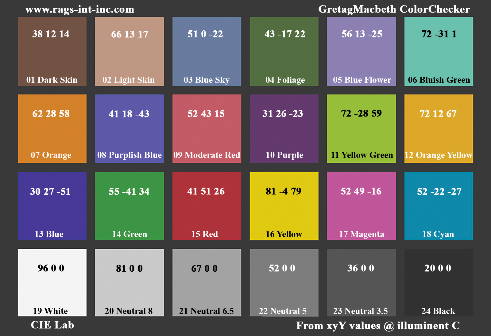
GretagMacbeth Color Checker Numeric Values and Middle Gray

The human eye perceives half scene brightness not as the linear 50% of the present energy (linear nature values) but as 18% of the overall brightness. We are biased to perceive more information in the dark and contrast areas. A Macbeth chart helps with calibrating back into a photographic capture into this “human perspective” of the world.


https://en.wikipedia.org/wiki/Middle_gray


In photography, painting, and other visual arts, middle gray or middle grey is a tone that is perceptually about halfway between black and white on a lightness scale in photography and printing, it is typically defined as 18% reflectance in visible light


Light meters, cameras, and pictures are often calibrated using an 18% gray card[4][5][6] or a color reference card such as a ColorChecker. On the assumption that 18% is similar to the average reflectance of a scene, a grey card can be used to estimate the required exposure of the film.


https://en.wikipedia.org/wiki/ColorChecker


https://photo.stackexchange.com/questions/968/how-can-i-correctly-measure-light-using-a-built-in-camera-meter


The exposure meter in the camera does not know whether the subject itself is bright or not. It simply measures the amount of light that comes in, and makes a guess based on that. The camera will aim for 18% gray independently, meaning if you take a photo of an entirely white surface, and an entirely black surface you should get two identical images which both are gray (at least in theory). Thus enters the Macbeth chart.


Note that Chroma Key Green is reasonably close to an 18% gray reflectance.

http://www.rags-int-inc.com/PhotoTechStuff/MacbethTarget/


No Camera Data


https://upload.wikimedia.org/wikipedia/commons/b/b4/CIE1931xy_ColorChecker_SMIL.svg


RGB coordinates of the Macbeth ColorChecker


https://pdfs.semanticscholar.org/0e03/251ad1e6d3c3fb9cb0b1f9754351a959e065.pdf

(more…)

VFX pipeline – Render Wall management topics
/ Featured, production

1: Introduction Title: Managing a VFX Facility’s Render Wall

  • Briefly introduce the importance of managing a VFX facility’s render wall.
  • Highlight how efficient management contributes to project timelines and overall productivity.


2: Daily Overview Title: Daily Management Routine

  • Monitor Queues: Begin each day by reviewing render queues to assess workload and priorities.
  • Resource Allocation: Allocate resources based on project demands and available hardware.
  • Job Prioritization: Set rendering priorities according to project deadlines and importance.
  • Queue Optimization: Adjust queue settings to maximize rendering efficiency.


3: Resource Allocation Title: Efficient Resource Management

  • Hardware Utilization: Distribute rendering tasks across available machines for optimal resource usage.
  • Balance Workloads: Avoid overloading specific machines while others remain underutilized.
  • Consider Off-Peak Times: Schedule resource-intensive tasks during off-peak hours to enhance overall performance.


4: Job Prioritization Title: Prioritizing Rendering Tasks

  • Deadline Sensitivity: Give higher priority to tasks with imminent deadlines to ensure timely delivery.
  • Critical Shots: Identify shots crucial to the project’s narrative or visual impact for prioritization.
  • Dependent Shots: Sequence shots that depend on others should be prioritized together.


5: Queue Optimization and Reporting Title: Streamlining Render Queues

  • Dependency Management: Set up dependencies to ensure shots are rendered in the correct order.
  • Error Handling: Implement automated error detection and requeueing mechanisms.
  • Progress Tracking: Regularly monitor rendering progress and update stakeholders.
  • Data Management: Archive completed renders and remove redundant data to free up storage.
  • Reporting: Provide daily reports on rendering status, resource usage, and potential bottlenecks.


6: Conclusion Title: Enhancing VFX Workflow

  • Effective management of a VFX facility’s render wall is essential for project success.
  • Daily monitoring, resource allocation, job prioritization, queue optimization, and reporting are key components.
  • A well-managed render wall ensures efficient production, timely delivery, and overall project success.
Types of Film Lights and their efficiency – CRI, Color Temperature and Luminous Efficacy
/ colour, composition, Featured, lighting

nofilmschool.com/types-of-film-lights


“Not every light performs the same way. Lights and lighting are tricky to handle. You have to plan for every circumstance. But the good news is, lighting can be adjusted. Let’s look at different factors that affect lighting in every scene you shoot. ”

Use CRI, Luminous Efficacy and color temperature controls to match your needs.


Color Temperature
Color temperature describes the “color” of white light by a light source radiated by a perfect black body at a given temperature measured in degrees Kelvin


http://www.pixelsham.com/2019/10/18/color-temperature/


CRI
“The Color Rendering Index is a measurement of how faithfully a light source reveals the colors of whatever it illuminates, it describes the ability of a light source to reveal the color of an object, as compared to the color a natural light source would provide. The highest possible CRI is 100. A CRI of 100 generally refers to a perfect black body, like a tungsten light source or the sun. ”


https://www.studiobinder.com/blog/what-is-color-rendering-index/


https://en.wikipedia.org/wiki/Color_rendering_index


Light source CCT (K) CRI
Low-pressure sodium (LPS/SOX) 1800 −44
Clear mercury-vapor 6410 17
High-pressure sodium (HPS/SON) 2100 24
Coated mercury-vapor 3600 49
Halophosphate warm-white fluorescent 2940 51
Halophosphate cool-white fluorescent 4230 64
Tri-phosphor warm-white fluorescent 2940 73
Halophosphate cool-daylight fluorescent 6430 76
“White” SON 2700 82
Standard LED Lamp 2700–5000 83
Quartz metal halide 4200 85
Tri-phosphor cool-white fluorescent 4080 89
High-CRI LED lamp (blue LED) 2700–5000 95
Ceramic discharge metal-halide lamp 5400 96
Ultra-high-CRI LED lamp (violet LED) 2700–5000 99
Incandescent/halogen bulb 3200 100


Luminous Efficacy
Luminous efficacy is a measure of how well a light source produces visible light, watts out versus watts in, measured in lumens per watt. In other words it is a measurement that indicates the ability of a light source to emit visible light using a given amount of power. It is a ratio of the visible energy to the power that goes into the bulb.


FILM LIGHT TYPES

https://www.studiobinder.com/blog/video-lighting-kits/?utm_campaign=Weekly_Newsletter&utm_medium=email&utm_source=sendgrid&utm_term=production-lighting&utm_content=production-lighting


Consumer light types


https://www.researchgate.net/figure/Emission-spectra-of-different-light-sources-a-incandescent-tungsten-light-bulb-b_fig1_312320039


http://dev.informationdisplay.org/IDArchive/2015/NovemberDecember/FrontlineTechnologyCandleLikeEmission.aspx


Tungsten Lights
Light interiors and match domestic places or office locations. Daylight.

Advantages of Tungsten Lights
Almost perfect color rendition
Low cost
Does not use mercury like CFLs (fluorescent) or mercury vapor lights
Better color temperature than standard tungsten
Longer life than a conventional incandescent
Instant on to full brightness, no warm-up time, and it is dimmable

Disadvantages of Tungsten Lights
Extremely hot
High power requirement
The lamp is sensitive to oils and cannot be touched
The bulb is capable of blowing and sending hot glass shards outward. A screen or layer of glass on the outside of the lamp can protect users.


Hydrargyrum medium-arc iodide lights
HMI’s are used when high output is required. They are also used to recreate sun shining through windows or to fake additional sun while shooting exteriors. HMIs can light huge areas at once.

Advantages of HMI lights
High light output
Higher efficiency
High color temperature

Disadvantages of HMI lights:
High cost
High power requirement
Dims only to about 50%
the color temperature increases with dimming
HMI bulbs will explode is dropped and release toxic chemicals


Fluorescent
Fluorescent film lighting is achieved by laying multiple tubes next to each other, combining as many as you want for the desired brightness. The good news is you can choose your bulbs to either be warm or cool depending on the scenario you’re shooting. You want to get these bulbs close to the subject because they’re not great at opening up spaces. Fluorescent lighting is used to light interiors and is more compact and cooler than tungsten or HMI lighting.

Advantages of Fluorescent lights
High efficiency
Low power requirement
Low cost
Long lamp life
Cool
Capable of soft even lighting over a large area
Lightweight

Disadvantages of Fluorescent lights
Flicker
High CRI
Domestic tubes have low CRI & poor color rendition.


LED
LED’s are more and more common on film sets. You can use batteries to power them. That makes them portable and sleek – no messy cabled needed. You can rig your own panels of LED lights to fit any space necessary as well. LED’s can also power Fresnel style lamp heads such as the Arri L-series.

Advantages of LED light
Soft, even lighting
Pure light without UV-artifacts
High efficiency
Low power consumption, can be battery powered
Excellent dimming by means of pulse width modulation control
Long lifespan
Environmentally friendly
Insensitive to shock
No risk of explosion

Disadvantages of LED light
High cost.
LED’s are currently still expensive for their total light output


Light texture packs

Advanced Computer Vision with Python OpenCV and Mediapipe
/ Featured, production, python, software

https://www.freecodecamp.org/news/advanced-computer-vision-with-python/


https://www.freecodecamp.org/news/how-to-use-opencv-and-python-for-computer-vision-and-ai/


Working for a VFX (Visual Effects) studio provides numerous opportunities to leverage the power of Python and OpenCV for various tasks. OpenCV is a versatile computer vision library that can be applied to many aspects of the VFX pipeline. Here’s a detailed list of opportunities to take advantage of Python and OpenCV in a VFX studio:


  1. Image and Video Processing:
    • Preprocessing: Python and OpenCV can be used for tasks like resizing, color correction, noise reduction, and frame interpolation to prepare images and videos for further processing.
    • Format Conversion: Convert between different image and video formats using OpenCV’s capabilities.
  2. Tracking and Matchmoving:
    • Feature Detection and Tracking: Utilize OpenCV to detect and track features in image sequences, which is essential for matchmoving tasks to integrate computer-generated elements into live-action footage.
  3. Rotoscoping and Masking:
    • Segmentation and Masking: Use OpenCV for creating and manipulating masks and alpha channels for various VFX tasks, like isolating objects or characters from their backgrounds.
  4. Camera Calibration:
    • Intrinsic and Extrinsic Calibration: Python and OpenCV can help calibrate cameras for accurate 3D scene reconstruction and camera tracking.
  5. 3D Scene Reconstruction:
    • Stereoscopy: Use OpenCV to process stereoscopic image pairs for creating 3D depth maps and generating realistic 3D scenes.
    • Structure from Motion (SfM): Implement SfM techniques to create 3D models from 2D image sequences.
  6. Green Screen and Blue Screen Keying:
    • Chroma Keying: Implement advanced keying algorithms using OpenCV to seamlessly integrate actors and objects into virtual environments.
  7. Particle and Fluid Simulations:
    • Particle Tracking: Utilize OpenCV to track and manipulate particles in fluid simulations for more realistic visual effects.
  8. Motion Analysis:
    • Optical Flow: Implement optical flow algorithms to analyze motion patterns in footage, useful for creating dynamic VFX elements that follow the motion of objects.
  9. Virtual Set Extension:
    • Camera Projection: Use camera calibration techniques to project virtual environments onto physical sets, extending the visual scope of a scene.
  10. Color Grading:
    • Color Correction: Implement custom color grading algorithms to match the color tones and moods of different shots.
  11. Automated QC (Quality Control):
    • Artifact Detection: Develop Python scripts to automatically detect and flag visual artifacts like noise, flicker, or compression artifacts in rendered frames.
  12. Data Analysis and Visualization:
    • Performance Metrics: Use Python to analyze rendering times and optimize the rendering process.
    • Data Visualization: Generate graphs and charts to visualize render farm usage, project progress, and resource allocation.
  13. Automating Repetitive Tasks:
    • Batch Processing: Automate repetitive tasks like resizing images, applying filters, or converting file formats across multiple shots.
  14. Machine Learning Integration:
    • Object Detection: Integrate machine learning models (using frameworks like TensorFlow or PyTorch) to detect and track specific objects or elements within scenes.
  15. Pipeline Integration:
    • Custom Tools: Develop Python scripts and tools to integrate OpenCV-based processes seamlessly into the studio’s pipeline.
  16. Real-time Visualization:
    • Live Previsualization: Implement real-time OpenCV-based visualizations to aid decision-making during the preproduction stage.
  17. VR and AR Integration:
    • Augmented Reality: Use Python and OpenCV to integrate virtual elements into real-world footage, creating compelling AR experiences.
  18. Camera Effects:
    • Lens Distortion: Correct lens distortions and apply various camera effects using OpenCV, contributing to the desired visual style.


Interpolating frames from an EXR sequence using OpenCV can be useful when you have only every second frame of a final render and you want to create smoother motion by generating intermediate frames. However, keep in mind that interpolating frames might not always yield perfect results, especially if there are complex changes between frames. Here’s a basic example of how you might use OpenCV to achieve this:


import cv2
import numpy as np
import os

# Replace with the path to your EXR frames
exr_folder = "path_to_exr_frames"

# Replace with the appropriate frame extension and naming convention
frame_template = "frame_{:04d}.exr"

# Define the range of frame numbers you have
start_frame = 1
end_frame = 100
step = 2

# Define the output folder for interpolated frames
output_folder = "output_interpolated_frames"
os.makedirs(output_folder, exist_ok=True)

# Loop through the frame range and interpolate
for frame_num in range(start_frame, end_frame + 1, step):
    frame_path = os.path.join(exr_folder, frame_template.format(frame_num))
    next_frame_path = os.path.join(exr_folder, frame_template.format(frame_num + step))

    if os.path.exists(frame_path) and os.path.exists(next_frame_path):
        frame = cv2.imread(frame_path, cv2.IMREAD_ANYDEPTH | cv2.IMREAD_COLOR)
        next_frame = cv2.imread(next_frame_path, cv2.IMREAD_ANYDEPTH | cv2.IMREAD_COLOR)

        # Interpolate frames using simple averaging
        interpolated_frame = (frame + next_frame) / 2

        # Save interpolated frame
        output_path = os.path.join(output_folder, frame_template.format(frame_num))
        cv2.imwrite(output_path, interpolated_frame)

        print(f"Interpolated frame {frame_num}") # alternatively: print("Interpolated frame {}".format(frame_num))


Please note the following points:


  • The above example uses simple averaging to interpolate frames. More advanced interpolation methods might provide better results, such as motion-based algorithms like optical flow-based interpolation.
  • EXR files can store high dynamic range (HDR) data, so make sure to use cv2.IMREAD_ANYDEPTH flag when reading these files.
  • OpenCV might not support EXR format directly. You might need to use a library like exr to read and manipulate EXR files, and then convert them to OpenCV-compatible formats.
  • Consider the characteristics of your specific render when using interpolation. If there are large changes between frames, the interpolation might lead to artifacts.
  • Experiment with different interpolation methods and parameters to achieve the desired result.
  • For a more advanced and accurate interpolation, you might need to implement or use existing algorithms that take into account motion estimation and compensation.


Key/Fill ratios and scene composition using false colors

www.videomaker.com/article/c03/18984-how-to-calculate-contrast-ratios-for-more-professional-lighting-setups


To measure the contrast ratio you will need a light meter. The process starts with you measuring the main source of light, or the key light.


Get a reading from the brightest area on the face of your subject. Then, measure the area lit by the secondary light, or fill light. To make sense of what you have just measured you have to understand that the information you have just gathered is in F-stops, a measure of light. With each additional F-stop, for example going one stop from f/1.4 to f/2.0, you create a doubling of light. The reverse is also true; moving one stop from f/8.0 to f/5.6 results in a halving of the light.


Let’s say you grabbed a measurement from your key light of f/8.0. Then, when you measured your fill light area, you get a reading of f/4.0. This will lead you to a contrast ratio of 4:1 because there are two stops between f/4.0 and f/8.0 and each stop doubles the amount of light. In other words, two stops x twice the light per stop = four times as much light at f/8.0 than at f/4.0.


theslantedlens.com/2017/lighting-ratios-photo-video/


What Can’t Ratios Tell You?

Ratios are great but they don’t solve all the challenges of a lighting set up for a DP. Ratios help with the mood but there are a number of other factors that need to be considered as well.

1. Type of Lighting:

Soft light vs. Hard Light.  Ratios can’t help you determine whether to use soft light or hard light. You have to know what the differences are and when to employ them.

2. Direction of Lighting

Ratios can’t help you determine where the Key light should be coming from.

3. Color

Ratios are no good for color.  You have to develop your project and understand how the color temperature of lights impacts mood and feeling.


To get the most out of the images below you have to know what you are looking at. The FSI False Color is user adjustable (one of the reasons it is so powerful) and they way I have set it up reads like this.


RED = 3 Stops Over
Yellow = 2 Stops Over
Light Green = 1 Stop Over
Grey = Key
Teal = 1 Stop Under
Light Blue = 2 Stops Under
Dark Blue = 3 Stops Under
Black = 4 Stops Under


Replicating the fake color process through Foundry Nuke:

set cut_paste_input [stack 0]
version 13.2 v7
push $cut_paste_input
Expression {
expr0 "(r > 2) || (g > 2) || (b > 2) ? 3:0"
expr1 "((r > 1) && (r < 2)) || ((g > 1) && (g < 2)) || ((b > 1) && (b < 2))\n ? 2:0"
expr2 "((r > 0) && (r < 1)) || ((g > 0) && (g < 1)) || ((b > 0) && (b < 1))\n ? 1:0"
name Expression4
selected true
xpos 631
ypos 54
}
Blur {
size 100
filter quadratic
name Blur1
selected true
xpos 631
ypos 120
}


Blurring an image using the same scheme:

set cut_paste_input [stack 0]
version 13.2 v8
push $cut_paste_input
Dot {
name Dot27
selected true
xpos 446
ypos 2259
}
set N329d7800 [stack 0]
Expression {
expr0 "(r > 2) || (g > 2) || (b > 2) ? 3:0"
expr1 "((r > 1) && (r < 2)) || ((g > 1) && (g < 2)) || ((b > 1) && (b < 2))\n ? 2:0"
expr2 "((r > 0) && (r < 1)) || ((g > 0) && (g < 1)) || ((b > 0) && (b < 1))\n ? 1:0"
name Expression1
selected true
xpos 521
ypos 2167
}
set N66560500 [stack 0]
Shuffle2 {
fromInput1 {{0} B}
fromInput2 {{0} B}
mappings "4 black -1 -1 rgba.red 0 0 rgba.green 0 1 rgba.alpha 0 3 black -1 -1 rgba.blue 0 2 rgba.green 0 1 rgba.green 0 1"
name Shuffle7
selected true
xpos 621
ypos 2241
}
push $N329d7800
Copy {
inputs 2
from0 rgba.alpha
to0 rgba.alpha
name Copy1
selected true
xpos 621
ypos 2315
}
Blur {
size 50
maskChannelInput rgba.alpha
name Blur3
selected true
xpos 621
ypos 2384
}
push $N66560500
Shuffle2 {
fromInput1 {{0} B}
fromInput2 {{0} B}
mappings "4 black -1 -1 rgba.green 0 1 black -1 -1 rgba.red 0 0 rgba.blue 0 2 rgba.blue 0 2 rgba.blue 0 2 rgba.alpha 0 3"
name Shuffle1
selected true
xpos 730
ypos 2242
}
push $N329d7800
Copy {
inputs 2
from0 rgba.alpha
to0 rgba.alpha
name Copy2
selected true
xpos 793
ypos 2318
}
Blur {
size 100
maskChannelInput rgba.alpha
name Blur4
selected true
xpos 793
ypos 2380
}
Merge2 {
inputs 2
operation matte
name Merge3
selected true
xpos 621
ypos 2459
}
push $N66560500
Shuffle2 {
fromInput1 {{0} B}
fromInput2 {{0} B}
mappings "4 rgba.red 0 0 rgba.red 0 0 rgba.red 0 0 rgba.alpha 0 3 black -1 -1 rgba.blue 0 2 black -1 -1 rgba.green 0 1"
name Shuffle8
selected true
xpos 521
ypos 2241
}
push $N329d7800
Copy {
inputs 2
from0 rgba.alpha
to0 rgba.alpha
name Copy3
selected true
xpos 521
ypos 2315
}
Merge2 {
inputs 2
operation matte
name Merge5
selected true
xpos 521
ypos 2506
}


The two options together


set cut_paste_input [stack 0]
version 13.2 v8
push $cut_paste_input
Group {
 name FalseColorCompositionTest
 selected true
 xpos 389
 ypos 192
}
 BackdropNode {
  inputs 0
  name VIEWER_1
  xpos 458
  ypos -174
 }
 BackdropNode {
  inputs 0
  name VIEWER_2
  xpos 722
  ypos -108
  bdwidth 161
  bdheight 68
 }
 BackdropNode {
  inputs 0
  name VIEWER_3
  tile_color 0x8e8e8eff
  note_font_size 42
  xpos 738
  ypos 301
  bdheight 110
 }
 BackdropNode {
  inputs 0
  name VIEWER_4
  xpos 394
  ypos -43
 }
 Input {
  inputs 0
  name Input1
  xpos 467
  ypos -326
 }
 Dot {
  name DotIN
  xpos 501
  ypos -258
 }
 Dot {
  name Dot2
  label "\n"
  xpos 501
  ypos -144
 }
set N28599ad0 [stack 0]
 Dot {
  name Dot27
  xpos 611
  ypos -144
 }
set N2859e960 [stack 0]
 Expression {
  expr0 "(r > 2) || (g > 2) || (b > 2) ? 3:0"
  expr1 "((r > 1) && (r < 2)) || ((g > 1) && (g < 2)) || ((b > 1) && (b < 2))\n ? 2:0"
  expr2 "((r > 0) && (r < 1)) || ((g > 0) && (g < 1)) || ((b > 0) && (b < 1))\n ? 1:0"
  name Expression4
  xpos 828
  ypos -148
 }
push $N2859e960
 Expression {
  expr0 "(r > .6) || (g > .6) || (b > .6) ? 3:0"
  expr1 "((r > .22) && (r < .6)) || ((g > .22) && (g < .6)) || ((b > .22) && (b < .6))\n ? 2:0"
  expr2 "((r > 0) && (r < .22)) || ((g > 0) && (g < .22)) || ((b > 0) && (b < .22))\n ? 1:0"
  name Expression1
  xpos 710
  ypos -186
 }
 Switch {
  inputs 2
  name Switch1
  xpos 760
  ypos -78
 }
set N28650240 [stack 0]
 Dot {
  name Dot1
  xpos 878
  ypos 5
 }
set N286582c0 [stack 0]
 Shuffle2 {
  fromInput1 {{0} B}
  fromInput2 {{0} B}
  mappings "4 black -1 -1 rgba.red 0 0 rgba.green 0 1 rgba.alpha 0 3 black -1 -1 rgba.blue 0 2 rgba.green 0 1 rgba.green 0 1"
  name Shuffle7
  xpos 844
  ypos 41
 }
push $N2859e960
 Copy {
  inputs 2
  from0 rgba.alpha
  to0 rgba.alpha
  name Copy1
  xpos 844
  ypos 115
 }
 Blur {
  size 100
  maskChannelInput rgba.alpha
  name Blur3
  xpos 844
  ypos 184
 }
push $N286582c0
 Shuffle2 {
  fromInput1 {{0} B}
  fromInput2 {{0} B}
  mappings "4 black -1 -1 rgba.green 0 1 black -1 -1 rgba.red 0 0 rgba.blue 0 2 rgba.blue 0 2 rgba.blue 0 2 rgba.alpha 0 3"
  name Shuffle1
  xpos 953
  ypos 42
 }
push $N2859e960
 Copy {
  inputs 2
  from0 rgba.alpha
  to0 rgba.alpha
  name Copy2
  xpos 953
  ypos 111
 }
 Blur {
  size 200
  maskChannelInput rgba.alpha
  name Blur4
  xpos 953
  ypos 173
 }
 Merge2 {
  inputs 2
  operation matte
  name Merge3
  xpos 844
  ypos 259
 }
push $N286582c0
 Shuffle2 {
  fromInput1 {{0} B}
  fromInput2 {{0} B}
  mappings "4 rgba.red 0 0 rgba.red 0 0 rgba.red 0 0 rgba.alpha 0 3 black -1 -1 rgba.blue 0 2 black -1 -1 rgba.green 0 1"
  name Shuffle8
  xpos 744
  ypos 41
 }
push $N2859e960
 Copy {
  inputs 2
  from0 rgba.alpha
  to0 rgba.alpha
  name Copy3
  xpos 744
  ypos 115
 }
 Merge2 {
  inputs 2
  operation matte
  name Merge5
  xpos 744
  ypos 354
 }
push $N28650240
push $N28599ad0
 Saturation {
  saturation 0
  name Saturation1
  xpos 398
  ypos -15
 }
push $N28599ad0
 ContactSheet {
  inputs 4
  width 6100
  height 2501
  rows 1
  center true
  name ContactSheet1
  xpos 482
  ypos 437
 }
 Dot {
  name DotOUT
  xpos 512
  ypos 553
 }
 Output {
  name Output1
  xpos 478
  ypos 630
 }
end_group


Python and TCL: Tips and Tricks for Foundry Nuke
/ Featured, production, python, software

www.andreageremia.it/tutorial_python_tcl.html

https://www.gatimedia.co.uk/list-of-knobs-2

https://learn.foundry.com/nuke/developers/63/ndkdevguide/knobs-and-handles/knobtypes.html


http://www.andreageremia.it/tutorial_python_tcl.html


http://thoughtvfx.blogspot.com/2012/12/nuke-tcl-tips.html


Check final image quality

https://www.compositingpro.com/tech-check-compositing-shot-in-nuke/

Local copy:
http://pixelsham.com/wp-content/uploads/2023/03/compositing_pro_tech_check_nuke_script.nk


Nuke tcl procedures
https://www.gatimedia.co.uk/nuke-tcl-procedures


Knobs
https://learn.foundry.com/nuke/developers/63/ndkdevguide/knobs-and-handles/knobtypes.html


# return to the top
nuke.Root().begin()
nuke.allNodes()
nuke.Root().end()


# check if Nuke is running in UI or batch mode
nuke.env['gui'] # True or False


# prformatted font to use in a text node:
liberation mono


# import node from a path
# Replace '/path/to/your/script.nk' with the actual path to your Nuke script
script_path = '/path/to/your/script.nk'
# Create the node in the script
mynode = nuke.nodePaste(script_path)
# or
mynode = nuke.scriptReadFile(script_path) #asynchronous so the code wont wait for its completion, mynode  is empty
# same as 
mynode = nuke.tcl('source "{}"'.format(script_path))
my node will be empty and it wont select the node either
# or synchronous
mynode = NukeUI.Scriptlets.loadScriptlet(script_path) 


# connect a knob on an internal node to a parent's knob
# add a python expression to the internal node's knob like:
nuke.thisNode().parent()['falseColors'].getValue()
# or the opposite
not nuke.thisNode().parent()['falseColors'].getValue()
# or as tcl expression
1- parent.thatNode.disable


# check session performance
Sebastian Schütt – Monitoring Nuke’s sessions performance
nuke.startPerformanceTimers() nuke.resetPerformanceTimers() nuke.stopPerformanceTimers() # set a project start and end frames new_frame_start = 1 new_frame_end = 100 project_settings = nuke.Root() project_settings['first_frame'].setValue(new_frame_start) project_settings['last_frame'].setValue(new_frame_end) # disable/enable a node newReadNode['disable'].setValue(True) # force refresh a node myNode['update'].execute() # or myNode.forceValidate() # pop up UI alert warning nuke.alert('prompt')   # return a given node hdriGenNode = nuke.toNode('HDRI_Light_Export') clampTo1 = nuke.toNode('HDRI_Light_Export.Clamp To 1')   # access nodes within a group nuke.toNode('GroupNodeName.nestedNodeName')   # access a knob on a node hdriGenNode.knob('checkbox').getValue()   # return the node type topNode.Class() nuke.selectedNode().Class() nuke.selectedNode().name()   # return nodes within a group hdriGenNode = nuke.toNode('HDRI_Light_Export') hdriGenNode.begin() sel = nuke.selectedNodes() hdriGenNode.end()   # nodes position node.setXpos( 111 ) node.setYpos( 222 ) xPos = node.xpos() yPos = node.ypos() print 'new x position is', xPos print 'new y position is', yPos # execute a node's button through python node['button'].execute() # add knobs div = nuke.Text_Knob('someTextKnob','') myNode.addKnob(div) lgt_name = nuke.EvalString_Knob('lgt1_name','LGT1 name', 'some text') # id, label, txt myNode.addKnob(lgt_name) lgt_size = nuke.XY_Knob('lgt1_size', 'LGT1 size') myNode.addKnob(lgt_size) lgt_3Dpos = nuke.XYZ_Knob('lgt1_3Dpos', 'LGT1 3D pos') myNode.addKnob(lgt_3Dpos) lgt_distance = nuke.Double_Knob('lgt1_distance', ' distance') myNode.addKnob(lgt_distance ) lgt_isSun = nuke.Boolean_Knob('lgt1_isSun', ' sun/HMI') myNode.addKnob(lgt_isSun ) lgt_mask_clr = nuke.AColor_Knob('lgt1_maskClr', 'LGT1 mask clr') lgt_mask_clr.setValue([0.12, 0.62, 0.115, 0.65]) lgt_mask_clr.setVisible(False) myNode.addKnob(lgt_mask_clr) # add tab group knob lightTab = nuke.Tab_Knob('lgt1_tabBegin', 'LGT1, nuke.TABBEGINGROUP) myNode.addKnob(lightTab) lightTab = nuke.Tab_Knob('lgt1_tabEnd', 'LGT1', nuke.TABENDGROUP) myNode.addKnob(lightTab) # note if you have only one tab and you are programmatically adding to the bottom of it # remove the last endGroup node to make sure the new knobs go into the tab myNode.removeKnob(myNode['endGroup']) # python script knob remove_script = """ node = nuke.thisNode() for knob in node.knobs(): print(knob) if "lgt%s" in knob: node.removeKnob(node.knobs()[knob]) node.begin() lightGizmo = nuke.toNode('lgt%s') nuke.delete(lightGizmo) node.end() """ % (str(length), str(length)) lgt_remove = nuke.PyScript_Knob('lgt1_remove', 'LGT1 Remove', remove_script) myNode.addKnob(lgt_remove ) # link checkbox to function through knobChanged hdriGenNode.knob('knobChanged').setValue(''' nk = nuke.thisNode() k = nuke.thisKnob() if ("Jabuka_checkbox" in k.name()): print 'ciao' ''') # knobChanged production example my_code = """ n = nuke.thisNode() k = nuke.thisKnob() if k.name()=="sheetOrSequence" or k.name()=="showPanel": #print(nuke.toNode(n.name() + '.MasterSwitch')['which'].getValue()) if nuke.toNode(n.name() + '.MasterSwitch')['which'].getValue() == 0.0: n['frameEnd'].setValue(nuke.toNode(n.name() + '.MasterSwitch')['masterAppendClip_lastFrame'].getValue()) elif nuke.toNode(n.name() + '.MasterSwitch')['which'].getValue() == 1.0 : n['frameEnd'].setValue(nuke.toNode(n.name() + '.MasterSwitch')['masterContactSheet_lastFrame'].getValue()) """ nuke.toNode("JonasCSheet1").knob("knobChanged").setValue(my_code) # retrieve the knobChanged callback node['knobChanged'].toScript() # nuke knobChanged callback https://corson.be/nuke_python_snippet/ # “knobChanged” is an “hidden” knob which holds code executed each time that we touch any node’s knob. # Thanks to that we can filter some user actions on the node and doing cool stuff like dynamically adding things inside a group. # This follows the node code = """ knob = nuke.thisKnob() if knob.name() == 'size': print "size : %s" % knob.value() """ nuke.selectedNode()["knobChanged"].setValue(code) def find_dependent_nodes(selected_node, targetClass): dependent_nodes = set() visited_nodes = set() def recursive_search(node): if node in visited_nodes: return visited_nodes.add(node) dependents = node.dependent() for dependent_node in dependents: print(dependent_node.Class()) if dependent_node.Class() == targetClass: dependent_nodes.add(dependent_node) recursive_search(dependent_node) recursive_search(selected_node) return dependent_nodes find_dependent_nodes(node, 'Write') # nuke changed through a nuke callback def myCallback(): # Code to execute when any checkbox knob changes print("Some checkbox value has changed!") n = nuke.thisNode() k = nuke.thisKnob() if k.name()=="myknob" or k.name()=="showPanel": print('do this') nuke.addKnobChanged(myCallback) nuke.removeKnobChanged(myCallback) # remove it first every time you wish to change the callback # nuke callback production example (note this will need to be saved in a place that nuke can retrieve: https://support.foundry.com/hc/en-us/articles/115000007364-Q100248-Adding-Callbacks-in-Nuke) def sheetOrSequenceCallback(): # Code to execute when any checkbox knob changes #print("Some checkbox value has changed!") n = nuke.thisNode() k = nuke.thisKnob() if k.name()=="sheetOrSequence" or k.name()=="showPanel": #print(nuke.toNode(n.name() + '.MasterSwitch')['which'].getValue()) if nuke.toNode(n.name() + '.MasterSwitch')['which'].getValue() == 0.0: n['frameEnd'].setValue(nuke.toNode(n.name() + '.MasterSwitch')['masterAppendClip_lastFrame'].getValue()) elif nuke.toNode(n.name() + '.MasterSwitch')['which'].getValue() == 1.0 : n['frameEnd'].setValue(nuke.toNode(n.name() + '.MasterSwitch')['masterContactSheet_lastFrame'].getValue()) # Add the callback function to the knob nuke.addKnobChanged(sheetOrSequenceCallback) nuke.removeKnobChanged(sheetOrSequenceCallback) # more about callbacks
# return all knobs for label, knob in sorted(jonasNode.knobs().items()): print(label, knob.value()) # remove a knob for label, knob in sorted(mynode.knobs().items()): if 'keyshot' in label.lower(): mynode.removeKnob(knob) # work inside a node group posNode.begin() posNode.end()   # move back to root level nuke.Root().begin() # Add a button link to docs import webbrowser browser = webbrowser.get('chrome') site = 'https://yoursite' browser.open(site)   # return all nodes nuke.allNodes() # python code inside a text node message [python -exec { import re import json output = 'hello' ... ... }] [python output]   # connect nodes blur.setInput(0, read) # label a node blur['label'].setValue("Size: [value size]\nChannels: [value channels]\nMix: [value mix]") # disconnect nodes node.setInput(0, None)   # arrange nodes for n in nuke.allNodes(): n.autoplace()   # snap them to closest grid for n in nuke.allNodes(): nuke.autoplaceSnap( n )   # help on commands help(nuke.Double_Knob)   # rename nodes node['name'].setValue('new') # query the format of an image at a given node level myNode.input(0).format().width()   # select given node all_nodes = nuke.allNodes() for i in all_nodes: i.knob("selected").setValue(False) myNode.setSelected(True)   # return the connected nodes metaNode.dependent()   # return the input node metaNode.input(0)   # copy and paste node nuke.toNode('original node').setSelected(True) nuke.nodeCopy(nukescripts.cut_paste_file()) nukescripts.clear_selection_recursive() newNode = nuke.nodePaste(nukescripts.cut_paste_file()) # copy and paste node alternative https://corson.be/nuke_python_snippet/ node = nuke.selectedNode() newNode = nuke.createNode(node.Class(), node.writeKnobs(nuke.WRITE_NON_DEFAULT_ONLY | nuke.TO_SCRIPT), inpanel=False) node.writeKnobs(nuke.WRITE_USER_KNOB_DEFS | nuke.WRITE_NON_DEFAULT_ONLY | nuke.TO_SCRIPT)   # set knob value metaNode.knob('operation').setValue('Avg Intensities')   # get knob value writeNode.knob('file').value() # get a pulldown choice knob label pulldown_knob = node[knob_name] pulldown_index = pulldown_knob.value() # Get the current index of the pulldown knob pulldown_label = pulldown_knob.enumName(pulldown_index) # link two knobs' attributes # add knob link k = nuke.Link_Knob('attr1_id','attr1') k.makeLink(node.name(), 'attr2_id.attr2')   # link two knobs between different nodes sel = nuke.selectedNode() lgt_colorspace = nuke.Link_Knob('colorspace', 'Colorspace') sel.addKnob(lgt_colorspace) Read1 = nuke.selectedNode() sel.knob('colorspace').makeLink(Read1.name(), 'colorspace') # link pulldown menus
Ben, how do I expression-link Pulldown Knobs?
This syntax can be read as {child node}.{knob} — link to {parent node}.{knob} nuke.toNode('lgtRenderStatistics.Text2').knob('yjustify').setExpression('lgtRenderStatistics.yjustify') nuke.toNode('lgtRenderStatistics.Text2').knob('xjustify').setExpression('lgtRenderStatistics.xjustify')   # create a grade node set to only red and change its gain mg = nuke.nodes.Grade(name='test2',channels='red') mg['white'].setValue(2) # remove a node nuke.delete(newNode)   # get one value out of an array paramater mynode.knob(pos_name).value()[0] mynode.knob(pos_name).value()[1]   # find all nodes of type write writeNodesList = [] for node in nuke.allNodes('Write'): writeNodesList.append(node)   # create an expression in python to connect parameters myNode.knob("ROI").setExpression("parent." + pos_name) # link knobs between nodes through an expression (https://learn.foundry.com/nuke/content/comp_environment/expressions/linking_expressions.html) Transform1.scale # connect two checkbox knobs so that one works the opposite of the other (False:True) node = nuke.toNode('myNode.Text2_all_sphericalcameratest_beauty') node.knob('disable').setExpression('parent.viewStats ? 0 : 1') # connect parameters between nodes at different level through an (non python) expression maskGradeNode.knob('white').setExpression('parent.parent.lgt1_maskClr') # connect parameters between nodes at different level through a python expression nuke.thisNode().parent()['sheetOrSequence'].getValue() # or using python in TCL [python {nuke.thisNode().parent()['sheetOrSequence'].getValue()}] # multiline python expression in TCL [python {nuke.thisNode().parent()['sheetOrSequence'].getValue()}] [python {print(nuke.thisNode())}] # multiline python expression from code with a return statement nuke.selectedNode().knob('which').setExpression('''[python -execlocal x = 2 for i in range(10): x += i ret = x]''', 0) # connect 2d knobs on the same node through a python expression nuke.thisNode()['TL'].getValue()[0] + ((nuke.thisNode()['TR'].getValue()[0] - nuke.thisNode()['TL'].getValue()[0])/2) # To add this as a python expression on each x and y of a 2d knob newLabel_expression_x = "[python nuke.thisNode()\['TL'\].getValue()\[0\] + ((nuke.thisNode()\['TR'\].getValue()\[0\] - nuke.thisNode()\['TL'\].getValue()\[0\])/2)]" newLabel_expression_y = "[python nuke.thisNode()\['TL'\].getValue()\[1\] + 10]" node['lightLabel'].setExpression(newLabel_expression_x, 0) node['lightLabel'].setExpression(newLabel_expression_y, 1) # note this may launch some errors when generating the node # a tcl expression seems to work best newLabel_expression_x = "lgt" + str(length) + "_tl.x() + 20" newLabel_expression_y = "lgt" + str(length) + "_tl.y() + 20" lgt_label.setExpression(newLabel_expression_x, 0) lgt_label.setExpression(newLabel_expression_y, 1) # load gizmo nuke.load('Offset')   # set knobs colors hdriGenNode.knob('add').setLabel("<span style="color: yellow;"&gt;Add Light") # or at creation, add knob with color lgt_LUX = nuke.Text_Knob('lgt%s_LUX' %str(length),"<font color='yellow'> LUX",'0') # id, label, txt # or when creating the knob manually: <font color='#FF0000'>Keyshot 1 or <font color='red'>Keyshot 1 # set color knob values hdriGenNode.knob('lgt_maskClr_1').setValue([0.0, 0.5, 0.0, 0.8]) hdriGenNode.knob('lgt_maskClr_1').setValue(0.4,3) # set only the alpha # return nuke file path nuke.root().knob('name').value()   # write metadata metadata_content = '{set %sName %s}\n{set %sMaxLuma %s}\n{set %sEV %s}\n{set %sLUX %s}\n{set %sPos2D %s}\n{set %sPos3D %s}\n{set %sDistance %s}\n{set %sScale %s}\n{set %sOutputPath %s}\n' % (lgtName, lgtCustomName, lgtName, str(maxL[0]), lgtName, str(lgt_EV), lgtName, str(lgt_LUX), lgtName, string.replace(str(pos2D),' ',''), lgtName, string.replace(str(pos3D),' ',''), lgtName, str(distance), lgtName, string.replace(str(scale),' ',''), lgtName, outputPath) metadataNode["metadata"].fromScript(metadata_content) # read metadata # metadata should be stored under the read node itself under one of the tabs readNode.metadata().get( 'exr/arnold/host/name' )   # return scene name nuke.root().knob('name').value()   # animate text by getting a knob's value of a specific node: [value Read1.first]   # animate text by getting a knob's value of current node: [value this.size]   # add to the menus mainMenu = nuke.menu( "Nodes" ) mainMenuItem = mainMenu.findItem( "NewMenuName" ) if not mainMenuItem : mainMenuItem = mainMenu.addMenu( "NewMenuName" ) subMenuItem = mainMenuItem.findItem( "subMenu" ) if not subMenuItem: subMenuItem = mainMenuItem.addMenu( "subMenu" ) return [ mainMenuItem ] menus = myMenus() for menu in menus: menu.addCommand('my tool', 'mytool.file.function()', None)   # add aov layer nuke.Layer(mynode, [mynode +'.red', mynode +'.green', mynode +'.blue', mynode +'.alpha'])   # onCreate options (like an onload option) # https://community.foundry.com/discuss/topic/106936/how-to-use-the-oncreate-callback # https://benmcewan.com/blog/2018/09/10/add-new-functionality-to-default-nodes-with-addoncreate/ # For example, you could do this: def setIt(): n = nuke.thisNode() k= n.knob( 'artist' ) user = envTools.getUser() k.setValue(user) nuke.addOnCreate(setIt, nodeClass = "") # retrieve the oncreate function sel = nuke.selectedNodes() code = sel[0]['onCreate'].getValue() print(code) # Or if you want to bake your code directly to a node: code = """ n = nuke.thisNode() k= n.knob( 'artist' ) user = envTools.getUser() k.setValue(user) """ nuke.selectedNode()["onCreate"].setValue(code) # Problem with onCreate is that it's run every time the node is created, which means even open a script will trigger the code.   # replace known nodes nodeToPaste = '''set cut_paste_input [stack 0] version 12.2 v10 push $cut_paste_input Group { name DeepToImage tile_color 0x60ff selected true xpos 862 ypos -3199 addUserKnob {20 DeepToImage} addUserKnob {6 volumetric_composition l "volumetric composition" +STARTLINE} volumetric_composition true } Input { inputs 0 name Input1 xpos -891 ypos -705 } DeepToImage { volumetric_composition {{parent.volumetric_composition}} name DeepToImage xpos -891 ypos -637 } ModifyMetaData { metadata { {remove exr/chunkCount ""} } name ModifyMetaData1 xpos -891 ypos -611 } Output { name Output1 xpos -891 ypos -530 } end_group ''' fileName = '/tmp/deleteme.cache' out_file = open(fileName, "w") out_file.write(str(nodeToPaste)) out_file.close() allNodes = nuke.allNodes() for i in allNodes: i.knob("selected").setValue(False) for node in allNodes: if 'DeepToImage' in node.name(): node.setSelected(True) newNode = nuke.nodePaste(fileName) nuke.delete(node) # force a knob on the same line hdriGenNode.addKnob(lgt_name) # stay on the same line lgt_lightGroup.clearFlag(nuke.STARTLINE) hdriGenNode.addKnob(lgt_lightGroup) # start a new line lgt_extractMode.setFlag(nuke.STARTLINE) hdriGenNode.addKnob(lgt_extractMode)   # text message per frame set cut_paste_input [stack 0] version 12.2 v10 push 0 push 0 push 0 push 0 Text2 { inputs 0 font_size_toolbar 100 font_width_toolbar 100 font_height_toolbar 100 message "MultiplyFloat.a 0.003\nMultiplyFloat2.a 0.35" old_message {{77 117 108 116 105 112 108 121 70 108 111 97 116 46 97 32 32 32 48 46 48 48 51 10 77 117 108 116 105 112 108 121 70 108 111 97 116 50 46 97 32 48 46 51 53} } box {175.2000122 896 1206.200012 1014} transforms {{0 2} } global_font_scale 0.5 center {1024 540} cursor_initialised true autofit_bbox false initial_cursor_position {{175.2000122 974.4000854} } group_animations {{0} imported: 0 selected: items: "root transform/"} animation_layers {{1 11 1024 540 0 0 1 1 0 0 0 0} } name Text20 selected true xpos 1197 ypos -132 } FrameRange { first_frame 1017 last_frame 1017 time "" name FrameRange19 selected true xpos 1197 ypos -77 } AppendClip { inputs 5 firstFrame 1017 meta_from_first false time "" name AppendClip3 selected true xpos 1433 } push 0 Reformat { format "2048 1080 0 0 2048 1080 1 2K_DCP" name Reformat4 selected true xpos 1843 ypos -251 } Merge2 { inputs 2 name Merge5 selected true xpos 1843 } push $cut_paste_input Reformat { format "2048 1080 0 0 2048 1080 1 2K_DCP" name Reformat5 selected true xpos 1715 ypos 80 } Merge2 { inputs 2 name Merge6 selected true xpos 1843 ypos 86 } # check negative pixels set cut_paste_input [stack 0] version 12.2 v10 push $cut_paste_input Expression { expr0 "r < 0 ? 1 : 0" expr1 "g < 0 ? 1 : 0" expr2 "b < 0 ? 1 : 0" name Expression4 selected true xpos 1032 ypos -106 } FilterErode { channels rgba size -1.3 name FilterErode4 selected true xpos 1032 ypos -58 } # check where the user is clicking on the viewer area import nuke from PySide2.QtWidgets import QApplication from PySide2.QtCore import QObject, QEvent, Qt from PySide2.QtGui import QMouseEvent class ViewerClickCallback(QObject): def eventFilter(self, obj, event): if event.type() == QEvent.MouseButtonPress and event.button() == Qt.LeftButton: # Mouse click detected mouse_pos = event.pos() print("Mouse clicked at position:", mouse_pos.x(), mouse_pos.y()) return super(ViewerClickCallback, self).eventFilter(obj, event) #Create an instance of the callback callback = ViewerClickCallback() #Install the event filter on the application qapp = QApplication.instance() qapp.installEventFilter(callback) qapp.removeEventFilter(callback) ## you can put this under a node's button and close the callback after a given mouse click ## OR closing the callback through a different button import nuke from PySide2.QtCore import QObject, QEvent, Qt from PySide2.QtWidgets import QApplication class ViewerClickCallback(QObject): def __init__(self, arg1): super().__init__() self.arg1 = arg1 def eventFilter(self, obj, event): if event.type() == QEvent.MouseButtonPress and event.button() == Qt.LeftButton: # Mouse click detected mouse_pos = event.pos() print("Mouse clicked at position:", mouse_pos.x(), mouse_pos.y(),'\n') if self.arg1 == 'bl': jonasNode['bl'].setValue([mouse_pos.x(), mouse_pos.y()]) qapp.removeEventFilter(callback) return super(ViewerClickCallback, self).eventFilter(obj, event) # Create an instance of the callback callback = ViewerClickCallback('bl') # Store the callback as a global variable nuke.root().knob('custom_callback').setValue(callback) # Install the event filter on the application qapp = QApplication.instance() qapp.installEventFilter(callback) ## on the second button: import nuke # Retrieve the callback object from the global variable callback = nuke.root().knob('custom_callback').value() # Retrieve the QApplication instance qapp = QApplication.instance() # Remove the event filter qapp.removeEventFilter(callback) # collect deepsamples for a given node nodelist = ['DeepSampleB_hdri','DeepSampleA_hdri','DeepSampleB_spheres','DeepSampleA_spheres','DeepSampleB_volume','DeepSampleA_volume','DeepSampleB_furmg','DeepSampleA_furmg','DeepSampleB_furfg','DeepSampleA_furfg','DeepSampleB_furbg','DeepSampleA_furbg','DeepSampleB_checkers','DeepSampleA_checkers'] nodelist = ['DeepSampleB_hdri'] finalSamplesList = [] for nodeName in nodelist: print(nodeName) finalSamplesList.append(nodeName) finalSampes = 0 for posX in range(0,1921): for posY in range(0,1081): nukeNode = nuke.toNode(nodeName) nukeNode['pos'].setValue([posX,posY]) current_posSamples = nukeNode['samples'].getValue() finalSamples = finalSamples + current_posSamples print(finalSamples) finalSamplesList.append(finalSamples) # false color expressions set cut_paste_input [stack 0] version 13.2 v8 push $cut_paste_input Expression { expr0 "(r > 2) || (g > 2) || (b > 2) ? 3:0" expr1 "((r > 1) && (r < 2)) || ((g > 1) && (g < 2)) || ((b > 1) && (b < 2))\n ? 2:0" expr2 "((r > 0) && (r < 1)) || ((g > 0) && (g < 1)) || ((b > 0) && (b < 1))\n ? 1:0" name Expression4 selected true xpos 90 ypos 1795 }

(more…)

Photography basics: Exposure Value vs Photographic Exposure vs Il/Luminance vs Pixel luminance measurements
/ Featured, lighting, photography

Also see: http://www.pixelsham.com/2015/05/16/how-aperture-shutter-speed-and-iso-affect-your-photos/


In photography, exposure value (EV) is a number that represents a combination of a camera’s shutter speed and f-number, such that all combinations that yield the same exposure have the same EV (for any fixed scene luminance).


The EV concept was developed in an attempt to simplify choosing among combinations of equivalent camera settings. Although all camera settings with the same EV nominally give the same exposure, they do not necessarily give the same picture. EV is also used to indicate an interval on the photographic exposure scale. 1 EV corresponding to a standard power-of-2 exposure step, commonly referred to as a stop


EV 0 corresponds to an exposure time of 1 sec and a relative aperture of f/1.0. If the EV is known, it can be used to select combinations of exposure time and f-number.


https://www.streetdirectory.com/travel_guide/141307/photography/exposure_value_ev_and_exposure_compensation.html

Note EV does not equal to photographic exposure. Photographic Exposure is defined as how much light hits the camera’s sensor. It depends on the camera settings mainly aperture and shutter speed. Exposure value (known as EV) is a number that represents the exposure setting of the camera.


Thus, strictly, EV is not a measure of luminance (indirect or reflected exposure) or illuminance (incidental exposure); rather, an EV corresponds to a luminance (or illuminance) for which a camera with a given ISO speed would use the indicated EV to obtain the nominally correct exposure. Nonetheless, it is common practice among photographic equipment manufacturers to express luminance in EV for ISO 100 speed, as when specifying metering range or autofocus sensitivity.


The exposure depends on two things: how much light gets through the lenses to the camera’s sensor and for how long the sensor is exposed. The former is a function of the aperture value while the latter is a function of the shutter speed. Exposure value is a number that represents this potential amount of light that could hit the sensor. It is important to understand that exposure value is a measure of how exposed the sensor is to light and not a measure of how much light actually hits the sensor. The exposure value is independent of how lit the scene is. For example a pair of aperture value and shutter speed represents the same exposure value both if the camera is used during a very bright day or during a dark night.


Each exposure value number represents all the possible shutter and aperture settings that result in the same exposure. Although the exposure value is the same for different combinations of aperture values and shutter speeds the resulting photo can be very different (the aperture controls the depth of field while shutter speed controls how much motion is captured).

EV 0.0 is defined as the exposure when setting the aperture to f-number 1.0 and the shutter speed to 1 second. All other exposure values are relative to that number. Exposure values are on a base two logarithmic scale. This means that every single step of EV – plus or minus 1 – represents the exposure (actual light that hits the sensor) being halved or doubled.

https://www.streetdirectory.com/travel_guide/141307/photography/exposure_value_ev_and_exposure_compensation.html


Formula

https://en.wikipedia.org/wiki/Exposure_value


https://www.scantips.com/lights/math.html


which means   2EV = N² / t

where

  • N is the relative aperture (f-number) Important: Note that f/stop values must first be squared in most calculations
  • t is the exposure time (shutter speed) in seconds

EV 0 corresponds to an exposure time of 1 sec and an aperture of f/1.0.

Example: If f/16 and 1/4 second, then this is:

(N² / t) = (16 × 16 ÷ 1/4) = (16 × 16 × 4) = 1024.

Log₂(1024) is EV 10. Meaning, 210 = 1024.


Collecting photographic exposure using Light Meters

https://photo.stackexchange.com/questions/968/how-can-i-correctly-measure-light-using-a-built-in-camera-meter

The exposure meter in the camera does not know whether the subject itself is bright or not. It simply measures the amount of light that comes in, and makes a guess based on that. The camera will aim for 18% gray, meaning if you take a photo of an entirely white surface, and an entirely black surface you should get two identical images which both are gray (at least in theory)

https://en.wikipedia.org/wiki/Light_meter

For reflected-light meters, camera settings are related to ISO speed and subject luminance by the reflected-light exposure equation:

where

  • N is the relative aperture (f-number)
  • t is the exposure time (“shutter speed”) in seconds
  • L is the average scene luminance
  • S is the ISO arithmetic speed
  • K is the reflected-light meter calibration constant


For incident-light meters, camera settings are related to ISO speed and subject illuminance by the incident-light exposure equation:

where

  • E is the illuminance (in lux)
  • C is the incident-light meter calibration constant


Two values for K are in common use: 12.5 (Canon, Nikon, and Sekonic) and 14 (Minolta, Kenko, and Pentax); the difference between the two values is approximately 1/6 EV.
For C a value of 250 is commonly used.


Nonetheless, it is common practice among photographic equipment manufacturers to also express luminance in EV for ISO 100 speed. Using K = 12.5, the relationship between EV at ISO 100 and luminance L is then :

L = 2(EV-3)


The situation with incident-light meters is more complicated than that for reflected-light meters, because the calibration constant C depends on the sensor type. Illuminance is measured with a flat sensor; a typical value for C is 250 with illuminance in lux. Using C = 250, the relationship between EV at ISO 100 and illuminance E is then :


E = 2.5 * 2(EV)


https://nofilmschool.com/2018/03/want-easier-and-faster-way-calculate-exposure-formula

Three basic factors go into the exposure formula itself instead: aperture, shutter, and ISO. Plus a light meter calibration constant.

f-stop²/shutter (in seconds) = lux * ISO/C


If you at least know four of those variables, you’ll be able to calculate the missing value.

So, say you want to figure out how much light you’re going to need in order to shoot at a certain f-stop. Well, all you do is plug in your values (you should know the f-stop, ISO, and your light meter calibration constant) into the formula below:

lux = C (f-stop²/shutter (in seconds))/ISO


Exposure Value Calculator:

https://www.vroegop.nu/exposure-value-calculator/


From that perspective, an exposure stop is a measurement of Exposure and provides a universal linear scale to measure the increase and decrease in light, exposed to the image sensor, due to changes in shutter speed, iso & f-stop.
+-1 stop is a doubling or halving of the amount of light let in when taking a photo.
1 EV is just another way to say one stop of exposure change.


One major use of EV (Exposure Value) is just to measure any change of exposure, where one EV implies a change of one stop of exposure. Like when we compensate our picture in the camera.


If the picture comes out too dark, our manual exposure could correct the next one by directly adjusting one of the three exposure controls (f/stop, shutter speed, or ISO). Or if using camera automation, the camera meter is controlling it, but we might apply +1 EV exposure compensation (or +1 EV flash compensation) to make the result goal brighter, as desired. This use of 1 EV is just another way to say one stop of exposure change.


On a perfect day the difference from sampling the sky vs the sun exposure with diffusing spot meters is about 3.2 exposure difference.

 ~15.4 EV for the sun
 ~12.2 EV for the sky

That is as a ballpark. All still influenced by surroundings, accuracy parameters, fov of the sensor…


EV calculator

https://www.scantips.com/lights/evchart.html#calc

http://www.fredparker.com/ultexp1.htm


Exposure value is basically used to indicate an interval on the photographic exposure scale, with a difference of 1 EV corresponding to a standard power-of-2 exposure step, also commonly referred to as a “stop”.


https://contrastly.com/a-guide-to-understanding-exposure-value-ev/


Retrieving photographic exposure from an image

All you can hope to measure with your camera and some images is the relative reflected luminance. Even if you have the camera settings. https://en.wikipedia.org/wiki/Relative_luminance


If you REALLY want to know the amount of light in absolute radiometric units, you’re going to need to use some kind of absolute light meter or measured light source to calibrate your camera. For references on how to do this, see: Section 2.5 Obtaining Absolute Radiance from http://www.pauldebevec.com/Research/HDR/debevec-siggraph97.pdf
 

IF you are still trying to gauge relative brightness, the level of the sun in Nuke can vary, but it should be in the thousands. Ie: between 30,000 and 65,0000 rgb value depending on time of the day, season and atmospherics.


The values for a 12 o’clock sun, with the sun sampled at EV 15.5 (shutter 1/30, ISO 100, F22) is 32.000 RGB max values (or 32,000 pixel luminance).
The thing to keep an eye for is the level of contrast between sunny side/fill side.  The terminator should be quite obvious,  there can be up to 3 stops difference between fill/key in sunny lit objects.


Note: In Foundry’s Nuke, the software will map 18% gray to whatever your center f/stop is set to in the viewer settings (f/8 by default… change that to EV by following the instructions below).
You can experiment with this by attaching an Exposure node to a Constant set to 0.18, setting your viewer read-out to Spotmeter, and adjusting the stops in the node up and down. You will see that a full stop up or down will give you the respective next value on the aperture scale (f8, f11, f16 etc.).
One stop doubles or halves the amount or light that hits the filmback/ccd, so everything works in powers of 2.
So starting with 0.18 in your constant, you will see that raising it by a stop will give you .36 as a floating point number (in linear space), while your f/stop will be f/11 and so on.

If you set your center stop to 0 (see below) you will get a relative readout in EVs, where EV 0 again equals 18% constant gray.
Note: make sure to set your Nuke read node to ‘raw data’


In other words. Setting the center f-stop to 0 means that in a neutral plate, the middle gray in the macbeth chart will equal to exposure value 0. EV 0 corresponds to an exposure time of 1 sec and an aperture of f/1.0.


To switch Foundry’s Nuke’s SpotMeter to return the EV of an image, click on the main viewport, and then press s, this opens the viewer’s properties. Now set the center f-stop to 0 in there. And the SpotMeter in the viewport will change from aperture and fstops to EV.


If you are trying to gauge the EV from the pixel luminance in the image:
– Setting the center f-stop to 0 means that in a neutral plate, the middle 18% gray will equal to exposure value 0.
– So if EV 0 = 0.18 middle gray in nuke which equal to a pixel luminance of 0.18, doubling that value, doubles the EV.

.18 pixel luminance = 0EV
.36 pixel luminance = 1EV
.72 pixel luminance = 2EV
1.46 pixel luminance = 3EV
...


This is a Geometric Progression function: xn = ar(n-1)

The most basic example of this function is 1,2,4,8,16,32,… The sequence starts at 1 and doubles each time, so

  • a=1 (the first term)
  • r=2 (the “common ratio” between terms is a doubling)

And we get:

{a, ar, ar2, ar3, … }

= {1, 1×2, 1×22, 1×23, … }

= {1, 2, 4, 8, … }

In this example the function translates to: n = 2(n-1)
You can graph this curve through this expression: x = 2(y-1)  :

You can go back and forth between the two values through a geometric progression function and a log function:

(Note: in a spreadsheet this is: = POWER(2; cell# -1)  and  =LOG(cell#, 2)+1) )

2(y-1) log2(x)+1
x y
1 1
2 2
4 3
8 4
16 5
32 6
64 7
128 8
256 9
512 10
1024 11
2048 12
4096 13


Translating this into a geometric progression between an image pixel luminance and EV:

(more…)

HDRI Median Cut plugin
/ Featured, lighting, software

www.hdrlabs.com/picturenaut/plugins.html


Note. The Median Cut algorithm is typically used for color quantization, which involves reducing the number of colors in an image while preserving its visual quality. It doesn’t directly provide a way to identify the brightest areas in an image. However, if you’re interested in identifying the brightest areas, you might want to look into other methods like thresholding, histogram analysis, or edge detection, through openCV for example.


Here is an openCV example:


# bottom left coordinates = 0,0
import numpy as np
import cv2

# Load the HDR or EXR image
image = cv2.imread('your_image_path.exr', cv2.IMREAD_UNCHANGED)  # Load as-is without modification

# Calculate the luminance from the HDR channels (assuming RGB format)
luminance = np.dot(image[..., :3], [0.299, 0.587, 0.114])

# Set a threshold value based on estimated EV
threshold_value = 2.4  # Estimated threshold value based on 4.8 EV

# Apply the threshold to identify bright areas
# The luminance array contains the calculated luminance values for each pixel in the image. # The threshold_value is a user-defined value that represents a cutoff point, separating "bright" and "dark" areas in terms of perceived luminance.
thresholded = (luminance > threshold_value) * 255 

# Convert the thresholded image to uint8 for contour detection 
thresholded = thresholded.astype(np.uint8) 

# Find contours of the bright areas 
contours, _ = cv2.findContours(thresholded, cv2.RETR_EXTERNAL, cv2.CHAIN_APPROX_SIMPLE) 

# Create a list to store the bounding boxes of bright areas 
bright_areas = [] 

# Iterate through contours and extract bounding boxes for contour in contours: 
x, y, w, h = cv2.boundingRect(contour) 

# Adjust y-coordinate based on bottom-left origin 
y_bottom_left_origin = image.shape[0] - (y + h) bright_areas.append((x, y_bottom_left_origin, x + w, y_bottom_left_origin + h)) 

# Store as (x1, y1, x2, y2) 
# Print the identified bright areas 
print("Bright Areas (x1, y1, x2, y2):") for area in bright_areas: print(area)


More details


Luminance and Exposure in an EXR Image:

  • An EXR (Extended Dynamic Range) image format is often used to store high dynamic range (HDR) images that contain a wide range of luminance values, capturing both dark and bright areas.
  • Luminance refers to the perceived brightness of a pixel in an image. In an RGB image, luminance is often calculated using a weighted sum of the red, green, and blue channels, where different weights are assigned to each channel to account for human perception.
  • In an EXR image, the pixel values can represent radiometrically accurate scene values, including actual radiance or irradiance levels. These values are directly related to the amount of light emitted or reflected by objects in the scene.


The luminance line is calculating the luminance of each pixel in the image using a weighted sum of the red, green, and blue channels. The three float values [0.299, 0.587, 0.114] are the weights used to perform this calculation.


These weights are based on the concept of luminosity, which aims to approximate the perceived brightness of a color by taking into account the human eye’s sensitivity to different colors. The values are often derived from the NTSC (National Television System Committee) standard, which is used in various color image processing operations.


Here’s the breakdown of the float values:

  • 0.299: Weight for the red channel.
  • 0.587: Weight for the green channel.
  • 0.114: Weight for the blue channel.


The weighted sum of these channels helps create a grayscale image where the pixel values represent the perceived brightness. This technique is often used when converting a color image to grayscale or when calculating luminance for certain operations, as it takes into account the human eye’s sensitivity to different colors.


For the threshold, remember that the exact relationship between EV values and pixel values can depend on the tone-mapping or normalization applied to the HDR image, as well as the dynamic range of the image itself.


To establish a relationship between exposure and the threshold value, you can consider the relationship between linear and logarithmic scales:

  1. Linear and Logarithmic Scales:
    • Exposure values in an EXR image are often represented in logarithmic scales, such as EV (exposure value). Each increment in EV represents a doubling or halving of the amount of light captured.
    • Threshold values for luminance thresholding are usually linear, representing an actual luminance level.
  2. Conversion Between Scales:
    • To establish a mathematical relationship, you need to convert between the logarithmic exposure scale and the linear threshold scale.
    • One common method is to use a power function. For instance, you can use a power function to convert EV to a linear intensity value.
    threshold_value = base_value * (2 ** EV)

    Here, EV is the exposure value, base_value is a scaling factor that determines the relationship between EV and threshold_value, and 2 ** EV is used to convert the logarithmic EV to a linear intensity value.

  3. Choosing the Base Value:
    • The base_value factor should be determined based on the dynamic range of your EXR image and the specific luminance values you are dealing with.
    • You may need to experiment with different values of base_value to achieve the desired separation of bright areas from the rest of the image.


Let’s say you have an EXR image with a dynamic range of 12 EV, which is a common range for many high dynamic range images. In this case, you want to set a threshold value that corresponds to a certain number of EV above the middle gray level (which is often considered to be around 0.18).

Here’s an example of how you might determine a base_value to achieve this:


# Define the dynamic range of the image in EV
dynamic_range = 12

# Choose the desired number of EV above middle gray for thresholding
desired_ev_above_middle_gray = 2

# Calculate the threshold value based on the desired EV above middle gray
threshold_value = 0.18 * (2 ** (desired_ev_above_middle_gray / dynamic_range))

print("Threshold Value:", threshold_value)
Cinematographers Blueprint 300dpi poster

The 300dpi digital poster is now available to all PixelSham.com subscribers.


If you have already subscribed and wish a copy, please send me a note through the contact page.

copypastecharacter.com – alphabets, special characters and symbols library
/ Featured, production, reference

https://www.copypastecharacter.com


Most used ones:

Alt + 0149   •  bullet point
Alt + 0153   ™  trademark symbol
Alt + 0169  ©  copyright symbol
Alt + 0174  ®  registered ­ trademark symbol
Alt + 0176  °  degree symbol
Alt + 0177   ±  plus-or-minus sign
Alt + 0215  ×  multi­plication sign
Alt + 12  ♀  female sign
Alt + 11  ♂  m­ale sign
Alt + 13  ♪  e­ighth note
Alt + 14  ♫  ­beamed eighth note
Alt + 251  √  square root check mark
Alt + 8236  ∞   ­infinity
Alt + 24  ↑  up arrow
Alt + 25  ↓  down arrow
Alt + 26  →  ri­ght arrow
Alt + 27  ←  l­eft arrow
Alt + 29  ↔  lef­t right arrow


All of them:

૱ ꠸ ┯ ┰ ┱ ┲ ❗ ► ◄ Ă ă 0 1 2 3 4 5 6 7 8 9 Ǖ ǖ Ꞁ ¤ ­ Ð ¢ ℥ Ω ℧ K ℶ ℷ ℸ ⅇ ⅊ ⚌ ⚍ ⚎ ⚏ ⚭ ⚮ ⌀ ⏑ ⏒ ⏓ ⏔ ⏕ ⏖ ⏗ ⏘ ⏙ ⏠ ⏡ ⏦ ᶀ ᶁ ᶂ ᶃ ᶄ ᶆ ᶇ ᶈ ᶉ ᶊ ᶋ ᶌ ᶍ ᶎ ᶏ ᶐ ᶑ ᶒ ᶓ ᶔ ᶕ ᶖ ᶗ ᶘ ᶙ ᶚ ᶸ ᵯ ᵰ ᵴ ᵶ ᵹ ᵼ ᵽ ᵾ ᵿ     ‌ ‍ ‎ ‏   ⁁ ⁊         ⸜ ⸝ ¶ ¥ £ ⅕ ⅙ ⅛ ⅔ ⅖ ⅗ ⅘ ⅜ ⅚ ⅐ ⅝ ↉ ⅓ ⅑ ⅒ ⅞ ← ↑ → ↓ ↔ ↕ ↖ ↗ ↘ ↙ ↚ ↛ ↜ ↝ ↞ ↟ ↠ ↡ ↢ ↣ ↤ ↥ ↦ ↧ ↨ ↩ ↪ ↫ ↬ ↭ ↮ ↯ ↰ ↱ ↲ ↳ ↴ ↵ ↶ ↷ ↸ ↹ ↺ ↻ ↼ ↽ ↾ ↿ ⇀ ⇁ ⇂ ⇃ ⇄ ⇅ ⇆ ⇇ ⇈ ⇉ ⇊ ⇋ ⇌ ⇍ ⇎ ⇏ ⇐ ⇑ ⇒ ⇓ ⇔ ⇕ ⇖ ⇗ ⇘ ⇙ ⇚ ⇛ ⇜ ⇝ ⇞ ⇟ ⇠ ⇡ ⇢ ⇣ ⇤ ⇥ ⇦ ⇨ ⇩ ⇪ ⇧ ⇫ ⇬ ⇭ ⇮ ⇯ ⇰ ⇱ ⇲ ⇳ ⇴ ⇵ ⇶ ⇷ ⇸ ⇹ ⇺ ⇻ ⇼ ⇽ ⇾ ⇿ ⟰ ⟱ ⟲ ⟳ ⟴ ⟵ ⟶ ⟷ ⟸ ⟹ ⟺ ⟻ ⟼ ⟽ ⟾ ⟿ ⤀ ⤁ ⤂ ⤃ ⤄ ⤅ ⤆ ⤇ ⤈ ⤉ ⤊ ⤋ ⤌ ⤍ ⤎ ⤏ ⤐ ⤑ ⤒ ⤓ ⤔ ⤕ ⤖ ⤗ ⤘ ⤙ ⤚ ⤛ ⤜ ⤝ ⤞ ⤟ ⤠ ⤡ ⤢ ⤣ ⤤ ⤥ ⤦ ⤧ ⤨ ⤩ ⤪ ⤫ ⤬ ⤭ ⤮ ⤯ ⤰ ⤱ ⤲ ⤳ ⤴ ⤵ ⤶ ⤷ ⤸ ⤹ ⤺ ⤻ ⤼ ⤽ ⤾ ⤿ ⥀ ⥁ ⥂ ⥃ ⥄ ⥅ ⥆ ⥇ ⥈ ⥉ ⥊ ⥋ ⥌ ⥍ ⥎ ⥏ ⥐ ⥑ ⥒ ⥓ ⥔ ⥕ ⥖ ⥗ ⥘ ⥙ ⥚ ⥛ ⥜ ⥝ ⥞ ⥟ ⥠ ⥡ ⥢ ⥣ ⥤ ⥥ ⥦ ⥧ ⥨ ⥩ ⥪ ⥫ ⥬ ⥭ ⥮ ⥯ ⥰ ⥱ ⥲ ⥳ ⥴ ⥵ ⥶ ⥷ ⥸ ⥹ ⥺ ⥻ ⥼ ⥽ ⥾ ⥿ ➔ ➘ ➙ ➚ ➛ ➜ ➝ ➞ ➝ ➞ ➟ ➠ ➡ ➢ ➣ ➤ ➥ ➦ ➧ ➨ ➩ ➩ ➪ ➫ ➬ ➭ ➮ ➯ ➱ ➲ ➳ ➴ ➵ ➶ ➷ ➸ ➹ ➺ ➻ ➼ ➽ ➾ ⬀ ⬁ ⬂ ⬃ ⬄ ⬅ ⬆ ⬇ ⬈ ⬉ ⬊ ⬋ ⬌ ⬍ ⬎ ⬏ ⬐ ⬑ ☇ ☈ ⏎ ⍃ ⍄ ⍅ ⍆ ⍇ ⍈ ⍐ ⍗ ⍌ ⍓ ⍍ ⍔ ⍏ ⍖ ♾ ⎌ ☊ ☋ ☌ ☍ ⌃ ⌄ ⌤ ⌅ ⌆ ⌇ ⚋ ⚊ ⌌ ⌍ ⌎ ⌏ ⌐ ⌑ ⌔ ⌕ ⌗ ⌙ ⌢ ⌣ ⌯ ⌬ ⌭ ⌮ ⌖ ⌰ ⌱ ⌲ ⌳ ⌴ ⌵ ⌶ ⌷ ⌸ ⌹ ⌺ ⌻ ⌼ ⍯ ⍰ ⌽ ⌾ ⌿ ⍀ ⍁ ⍂ ⍉ ⍊ ⍋ ⍎ ⍏ ⍑ ⍒ ⍕ ⍖ ⍘ ⍙ ⍚ ⍛ ⍜ ⍝ ⍞ ⍠ ⍟ ⍡ ⍢ ⍣ ⍤ ⍥ ⍨ ⍩ ⍦ ⍧ ⍬ ⍿ ⍪ ⍮ ⍫ ⍱ ⍲ ⍭ ⍳ ⍴ ⍵ ⍶ ⍷ ⍸ ⍹ ⍺ ⍼ ⍽ ⍾ ⎀ ⎁ ⎂ ⎃ ⎄ ⎅ ⎆ ⎉ ⎊ ⎋ ⎍ ⎎ ⎏ ⎐ ⎑ ⎒ ⎓ ⎔ ⎕ ⏣ ⌓ ⏥ ⏢ ⎖ ⎲ ⎳ ⎴ ⎵ ⎶ ⎸ ⎹ ⎺ ⎻ ⎼ ⎽ ⎾ ⎿ ⏀ ⏁ ⏂ ⏃ ⏄ ⏅ ⏆ ⏇ ⏈ ⏉ ⏉ ⏋ ⏌ ⏍ ⏐ ⏤ ⏚ ⏛ Ⓝ ℰ ⓦ !       ⌘ « » ‹ › ‘ ’ “ ” „ ‚ ❝ ❞ £ ¥ € $ ¢ ¬ ¶ @ § ® © ™ ° × π ± √ ‰ Ω ∞ ≈ ÷ ~ ≠ ¹ ² ³ ½ ¼ ¾ ‐ – — | ⁄ \ [ ] { } † ‡ … · • ●  ⌥ ⌃ ⇧ ↩ ¡ ¿ ‽ ⁂ ∴ ∵ ◊ ※ ← → ↑ ↓ ☜ ☞ ☝ ☟ ✔ ★ ☆ ♺ ☼ ☂ ☺ ☹ ☃ ✉ ✿ ✄ ✈ ✌ ✎ ♠ ♦ ♣ ♥ ♪ ♫ ♯ ♀ ♂ α ß Á á À à Å å Ä ä Æ æ Ç ç É é È è Ê ê Í í Ì ì Î î Ñ ñ Ó ó Ò ò Ô ô Ö ö Ø ø Ú ú Ù ù Ü ü Ž ž ₳ ฿ ¢ € ₡ ¢ ₢ ₵ ₫ £ £ ₤ ₣ ƒ ₲ ₭ ₥ ₦ ₱ $ $ ₮ ₩ ₩ ¥ ¥ ₴ ₰ ¤ ៛ ₪ ₯ ₠ ₧ ₨ ௹ ﷼ ㍐ ৲ ৳ ~ ƻ Ƽ ƽ ¹ ¸ ¬ ¨ ɂ ǁ ¯ Ɂ ǂ ¡ ´ ° ꟾ ¦ } { | . , · ] ) [ / _ \ ¿ º § ” * – + ( ! & % $ ¼ ¾ ½ ¶ © ® @ ẟ Ɀ ` Ȿ ^ ꜠ ꜡ ỻ ‘ = : ; < ꞌ Ꞌ ꞊ ꞁ ꞈ ꞉ > ? ÷ ℾ ℿ ℔ ℩ ℉ ⅀ ℈ þ ð Þ µ ª ꝋ ꜿ Ꜿ ⱽ ⱺ ⱹ ⱷ ⱶ Ⱶ ⱴ ⱱ Ɒ ⱦ ȶ ȴ ȣ Ȣ ȡ ȝ Ȝ ț ȋ Ȋ ȉ Ȉ ǯ Ǯ ǃ ǀ ƿ ƾ ƺ ƹ Ƹ Ʒ Ʋ ư ƪ ƣ Ƣ Ɵ ƛ Ɩ ƕ ƍ ſ ỽ ⸀ ⸁ ⸂ ⸃ ⸄ ⸅ ⸆ ⸇ ⸈ ⸉ ⸊ ⸋ ⸌ ⸍ ⸎ ⸏ ⸐ ⸑ ⸒ ⸔ ⸕ ▲ ▼ ◀ ▶ ◢ ◣ ◥ ◤ △ ▽ ◿ ◺ ◹ ◸ ▴ ▾ ◂ ▸ ▵ ▿ ◃ ▹ ◁ ▷ ◅ ▻ ◬ ⟁ ⧋ ⧊ ⊿ ∆ ∇ ◭ ◮ ⧩ ⧨ ⌔ ⟐ ◇ ◆ ◈ ⬖ ⬗ ⬘ ⬙ ⬠ ⬡ ⎔ ⋄ ◊ ⧫ ⬢ ⬣ ▰ ▪ ◼ ▮ ◾ ▗ ▖ ■ ∎ ▃ ▄ ▅ ▆ ▇ █ ▌ ▐ ▍ ▎ ▉ ▊ ▋ ❘ ❙ ❚ ▀ ▘ ▝ ▙ ▚ ▛ ▜ ▟ ▞ ░ ▒ ▓ ▂ ▁ ▬ ▔ ▫ ▯ ▭ ▱ ◽ □ ◻ ▢ ⊞ ⊡ ⊟ ⊠ ▣ ▤ ▥ ▦ ⬚ ▧ ▨ ▩ ⬓ ◧ ⬒ ◨ ◩ ◪ ⬔ ⬕ ❏ ❐ ❑ ❒ ⧈ ◰ ◱ ◳ ◲ ◫ ⧇ ⧅ ⧄ ⍁ ⍂ ⟡ ⧉ ⚬ ○ ⚪ ◌ ◍ ◎ ◯ ❍ ◉ ⦾ ⊙ ⦿ ⊜ ⊖ ⊘ ⊚ ⊛ ⊝ ● ⚫ ⦁ ◐ ◑ ◒ ◓ ◔ ◕ ⦶ ⦸ ◵ ◴ ◶ ◷ ⊕ ⊗ ⦇ ⦈ ⦉ ⦊ ❨ ❩ ⸨ ⸩ ◖ ◗ ❪ ❫ ❮ ❯ ❬ ❭ ❰ ❱ ⊏ ⊐ ⊑ ⊒ ◘ ◙ ◚ ◛ ◜ ◝ ◞ ◟ ◠ ◡ ⋒ ⋓ ⋐ ⋑ ╰ ╮ ╭ ╯ ⌒ ╳ ✕ ╱ ╲ ⧸ ⧹ ⌓ ◦ ❖ ✖ ✚ ✜

(more…)

Photography basics: Lumens vs Candelas (candle) vs Lux vs FootCandle vs Watts vs Irradiance vs Illuminance
/ colour, Featured, lighting, photography

https://www.translatorscafe.com/unit-converter/en-US/illumination/1-11/


The power output of a light source is measured using the unit of watts W. This is a direct measure to calculate how much power the light is going to drain from your socket and it is not relatable to the light brightness itself.

The amount of energy emitted from it per second. That energy comes out in a form of photons which we can crudely represent with rays of light coming out of the source. The higher the power the more rays emitted from the source in a unit of time.

Not all energy emitted is visible to the human eye, so we often rely on photometric measurements, which takes in account the sensitivity of human eye to different wavelenghts


https://pllight.com/understanding-lighting-metrics/

Candela is the basic unit of measure of light intensity from any point in a single direction from a light source. It measures the total volume of light within a certain beam angle and direction.
While the luminance of starlight is around 0.001 cd/m2, that of a sunlit scene is around 100,000 cd/m2, which is a hundred millions times higher. The luminance of the sun itself is approximately 1,000,000,000 cd/m2.


https://www.hdrsoft.com/resources/dri.html#bit-depth

To make it easier to represent values that vary so widely, it is common to use a logarithmic scale to plot the luminance. The scanline below represents the log base 10 of the luminance, so going from 0.1 to 1 is the same distance as going from 100 to 1000, for instance. A scene showing the interior of a room with a sunlit view outside the window, for instance, will have a dynamic range of approximately 100,000:1.


Lumen (lm) is the basic unit of measure for a light that is visible to the human eye. It indicates the total potential amount of light from a light source. If a uniform point source of 1 candela is at the center of a sphere with a 1ft2 radius with an opening of 1 ft2 at its surface, the quantity of light that passes through that opening is equal to 1 lumen. Since lumens are a photometric measurement for humans, we do not use this unit of measure for describing horticultural lighting.


Technically speaking, a Lumen is the SI unit of luminous flux, which is equal to the amount of light which is emitted per second in a unit solid angle of one steradian from a uniform source of one-candela intensity radiating in all directions.


Illuminance refers to the density of light over a given surface area, and is expressed in mostly LUX or lumens/m2.
Luminance refers to the amount of light emitted under various circumstances, and it is expressed mostly in LUMENS or candela/m2.


Lux (lx) or often Illuminance, is a photometric unit along a given area, which takes in account the sensitivity of human eye to different wavelenghts. It is the measure of light at a specific distance within a specific area at that distance. Often used to measure the incidental sun’s intensity. Its default unit describes the number of lumens visible in a square meter (lumen/m2). 100 lumens spread out over an area of 1 m2 will have an illuminance of 100 lx. The same 100 lumens spread out over 10 m2 produces a dimmer illuminance of only 10 lx.


The core difference between lux and lumens can be summarized as follows:

  • Lux is a measure of illuminance, the total amount of light that falls on a surface at a given distance
  • Lumens is a measure of luminous flux, the total amount of light emitted in all directions.


A footcandle describes the number of lumen per square foot. Therefore, one footcandle is equal to approximately 10.764 lx. This measure is only relevant for how we perceive light and is irrelevant for plant growth. Like lumens, lux and footcandles are not useful for describing horticultural lighting.


Color Rendering Index, or CRI, describes the ability of a light source to show an object’s color accurately in comparison to standardized colour samples under a reference light source. The highest value a light can achieve is a CRI of 100. Lower CRI values result in objects appearing unnatural or discolored. Under a light with a CRI of 100, an orange appears bright orange; under a light with a CRI of 70, the orange appears darker and bluer. This measure is dependent on how the human eye sees light, and so it is not a useful parameter for choosing horticultural lighting.


Correlated Color Temperature, or CCT, describes the color of a light source vs. a reference source when heated to a particular temperature, and is measured in degrees Kelvin (°K). The higher the CCT of a light source, the cooler the light’s color. For example, a very red light achieves a CCT of about 1000 K while a very blue light can achieve a CCT of about 10,000 K. Warm white lights will have a CCT around 2700 K (since they emit more energy at the red end of the spectrum), neutral white will be around 4000 K, and cool white around 5000 K (emitting more energy at the blue end of the spectrum). Similar to CRI, this measure is dependent on light perception by the human eye, and, once again, is not useful for describing or choosing horticultural lighting.


http://www.lumis.co.nz/reference-information/lighting-terminology

Light is a visible portion of electromagnetic radiation. Watts isn’t a measure of light output. Watts is actually a measure of total power output. Not all of the energy emitted by a light source is visible light – heat and invisible light waves (ex. infrared light) are also emitted. Lumens, on the other hand, will tell you the total visible light output of a source. For this reason, lumens (not watts) is the relevant unit of measure when you’re concerned about visibility. The higher the power the more rays emitted from the source in a unit of time.


Irradiance (radiant flux emitted by a surface per unit area aka watt per square meter) is a radiometric unit. As such also actually a measure of total power output.
Radiometric units are based on physical power, that means all wavelengths are weighted equally, while photometric units take into account the sensitivity of human eye to different wavelengths.
The weighting is determined by the luminosity function (which was measured for human eye and is an agreed-upon standard).


Converting Irradiance and Illuminance
http://www.dfisica.ubi.pt/~hgil/Fotometria/HandBook/ch07.html
There is a different conversion factor for every wavelength, so the spectral composition of light must be known to make the conversion.

At the most sensitive wavelegth to the human eye the conversion factor is

1.0 W/m2 = 683.002 lumen/m2 # at wavelength = 555nm (green)

That means the irradiance (power) to make 1 lumen is at it’s minimum at this wavelength (just 1.464 mW/m2).
Luminous efficiency is then the ratio between the actual number of lumens per watt and the theoretical maximum.
Incandescent light bulb has a luminous efficiency of 2% which is very poor. It’s because lot of it’s irradiance is only heat which is not visible. The luminosity function is zero for wavelengths outside the visible spectrum.


https://www.rapidtables.com/calc/light/lux-to-lumen-calculator.html


https://www.projectorpoint.co.uk/news/how-bright-should-my-projector-be/


https://dracobroadcast.eu/blogs/news/continuous-light-converting-guide


  • Watts (halogen) – A measure of energy consumed
  • Watts (HMI) – A measure of energy consumed
  • Watts (LED) – A measure of energy consumed
  • Lux – Lumens per square meter, illuminance at target
  • Footcandles – Lumens per square foot
  • Stops – Size of lens aperture
  • EV – Exposure Value
  • Lumens – Measure of amount of visible light, luminance from source
  • Candela – Measure of entire volume of lighting
  • NIT = Candela per square meter but is not part of the International System of Units
AnimationXpress.com interviews Daniele Tosti for TheCgCareer.com channel
/ Featured, ves

https://www.animationxpress.com/vfx/meet-daniele-tosti-a-senior-cg-artist-who-is-on-a-mission-to-inspire-the-next-generation-of-artists/


You’ve been in the VFX Industry for over a decade. Tell us about your journey.

It all started with my older brother giving me a Commodore64 personal computer as a gift back in the late 80′. I realised then I could create something directly from my imagination using this new digital media format. And, eventually, make a living in the process.
That led me to start my professional career in 1990. From live TV to games to animation. All the way to live action VFX in the recent years.

I really never stopped to crave to create art since those early days. And I have been incredibly fortunate to work with really great talent along the way, which made my journey so much more effective.


What inspired you to pursue VFX as a career?

An incredible combination of opportunities, really. The opportunity to express myself as an artist and earn money in the process. The opportunity to learn about how the world around us works and how best solve problems. The opportunity to share my time with other talented people with similar passions. The opportunity to grow and adapt to new challenges. The opportunity to develop something that was never done before. A perfect storm of creativity that fed my continuous curiosity about life and genuinely drove my inspiration.


Tell us about the projects you’ve particularly enjoyed working on in your career

I quite enjoyed working on live TV projects, as the combination of tight deadlines and high quality was quite an incredible learning platform as a professional artist. But working on large, high end live action feature projects was really where I learnt most of my trade. And gave me the most satisfaction.

Every film I worked on had some memorable experiences. Right from Avatar to Iron Man 3 to Jungle Book to The Planet of the Apes to The Hobbits to name a few.

But above all, the technical challenges and the high quality we reached in each and every of the projects that I worked on, the best memories come from working with amazing and skilled artists, from a variety of disciplines. As those were my true mentors and became my best friends.

Post Production, Animation, VFX, Motion Graphics, Video Editing …


What are some technologies and trends that you think are emerging in the VFX Industry?

In the last few years there has definitely been a bias from some major studios to make VFX a commodity. In the more negative sense of the word. When any product reaches a level of quality that attracts a mass of consumers and reaches a plateau of opportunities, large corporation tend to respond with maximising its sale values by leveraging marketing schemes and deliverable more than the core values of the product itself. This is often a commoditisation approach that tends to empower agents who are not necessarily knowledgeable of a product’s cycles, and in that process, lowering the quality of the product itself for the sake of profits. It is a pretty common event in modern society and it applies to any brand name, not just VFX.

One challenge with VFX’s technology and artistry is that it relies on the effectiveness of artists and visionaries for the most. And limiting the authority, ownerships and perspective of such a crowd has definitely directly impacted the overall quality of the last decade of productions, both technically and artistically. There are very few and apart creative forces who have been able to deliver project that one could identify as a truly creative breakthrough. While the majority of productions seem to have suffered from some of these commoditisation patterns.

The other bigger challenge with this current trend is that VFX, due to various, historical business arrangements, is often relying on unbalanced resources as well as very small and feeble economic cycles and margins. Which make the entire industry extremely susceptible to marketing failures and to unstable leadership. As a few recent bankruptcies have demonstrated.

It is taking some reasonable time for the VFX crowd to acknowledge these trends and learn to be profitable, as the majority has never been educated on fair business practices.

But. Thankfully, the VFX circle is also a crowd of extremely adaptable and talented individuals, who are quite capable at resolving issues, finding alternatives and leveraging their passion. Which I believe is one of the drives behind the current evolution in the use of artificial intelligence, virtual reality, virtual production, real time rendering, and so on.

There is still a long path ahead of us but I hope we are all learning ways to make our passion speaks in profitable ways for everyone.

It is also highly likely that, in a near future, larger software and hardware corporation, thanks to their more profitable business practices, large development teams and better understanding of marketing, will eventually take over a lot of the cycles that the current production houses currently run. And in that process allow creative studios to focus back on VFX artistry.


What effect has the pandemics-induced lockdown had on the industry?

It is still early to say. I fear that if live action production does not start soon, we may see some of the economic challenges I mention above. At both studio and artists’ scale. There is definitely a push from production houses to make large distribution clients understand the fragility of the moment, especially in relation to payment cycles and economic support. Thus, there is still a fair risk that the few studios which adopted a more commoditised view to production will make their artists pay some price for their choices.

But, any challenge brings opportunities. For example, there is finally some recognition into a momentum to rely on work-from-home as a feasible solution to a lot of the current office production’s limitations and general artistry restrictions. Which, while there is no win-win in this pandemic, could be a silver lining.


What would you say to the budding artists who wish to become CG artists or VFX professionals?

Follow your passion but treat this career as any other business.
Learn to be adaptable. Find a true balance between professional and family life. Carefully plan your future. And watch our channel to learn more about all these.

Being a VFX artist is fundamentally based on mistrust.
This because schedules, pipelines, technology, creative calls… all have a native and naive instability to them that causes everyone to grow a genuine but beneficial lack of trust in the status quoThe VFX motto: “Love everyone but trust no one” is born on that.


What inspired you to create a channel for aspiring artists?

As many fellow and respected artists, I love this industry, but I had to understand a lot of business practices at my own expenses.
You can learn tools, cycles and software from books and schools. But production life tends to drive its own rhythms and there are fewer opportunities to absorb those.

Along my career I had some challenges finding professional willing to share their time to invest into me. But I was still extremely fortunate to find other mentors who helped me to be economically and professionally successful in this business. I owe a lot to these people. I promised myself I would exchange that favour by helping other artists, myself.


What can students expect to learn from your channel?

I am excited to have the opportunity to fill some of the voids that the current education systems and industry may have. This by helping new artists with true life stories by some of the most accomplished and successful talents I met during my career. We will talk about technology trends as much as our life experiences as artists. Discussing career advises. Trying to look into the future of the industry. And suggesting professional tips. The aim through this mentor-ship is to inspire new generations to focus on what is more important for the VFX industry. Take responsibilities for their art and passions as much as their families.

And, in the process, to feel empowered to materialise from their imagination more and more of those creative, awe inspiring moments that this art form has gifted us with so far.


http://TheCGCareer.com


Photography basics: Production Rendering Resolution Charts
https://www.urtech.ca/2019/04/solved-complete-list-of-screen-resolution-names-sizes-and-aspect-ratios/


Resolution – Aspect Ratio 4:03 16:09 16:10 3:02 5:03 5:04
CGA 320 x 200
QVGA 320 x 240
VGA (SD, Standard Definition) 640 x 480
NTSC 720 x 480
WVGA 854 x 450
WVGA 800 x 480
PAL 768 x 576
SVGA 800 x 600
XGA 1024 x 768
not named 1152 x 768
HD 720 (720P, High Definition) 1280 x 720
WXGA 1280 x 800
WXGA 1280 x 768
SXGA 1280 x 1024
not named (768P, HD, High Definition) 1366 x 768
not named 1440 x 960
SXGA+ 1400 x 1050
WSXGA 1680 x 1050
UXGA (2MP) 1600 x 1200
HD1080 (1080P, Full HD) 1920 x 1080
WUXGA 1920 x 1200
2K 2048 x (any)
QWXGA 2048 x 1152
QXGA (3MP) 2048 x 1536
WQXGA 2560 x 1600
QHD (Quad HD) 2560 x 1440
QSXGA (5MP) 2560 x 2048
4K UHD (4K, Ultra HD, Ultra-High Definition) 3840 x 2160
QUXGA+ 3840 x 2400
IMAX 3D 4096 x 3072
8K UHD (8K, 8K Ultra HD, UHDTV) 7680 x 4320
10K  (10240×4320, 10K HD) 10240 x (any)
16K (Quad UHD, 16K UHD, 8640P) 15360 x 8640


(more…)

Photography basics: Solid Angle measures
/ Featured, lighting, photography

http://www.calculator.org/property.aspx?name=solid+angle


A measure of how large the object appears to an observer looking from that point. Thus. A measure for objects in the sky. Useful to retuen the size of the sun and moon… and in perspective, how much of their contribution to lighting. Solid angle can be represented in ‘angular diameter’ as well.

http://en.wikipedia.org/wiki/Solid_angle


http://www.mathsisfun.com/geometry/steradian.html


A solid angle is expressed in a dimensionless unit called a steradian (symbol: sr). By default in terms of the total celestial sphere and before atmospheric’s scattering, the Sun and the Moon subtend fractional areas of 0.000546% (Sun) and 0.000531% (Moon).


http://en.wikipedia.org/wiki/Solid_angle#Sun_and_Moon


On earth the sun is likely closer to 0.00011 solid angle after athmospheric scattering. The sun as perceived from earth has a diameter of 0.53 degrees. This is about 0.000064 solid angle.

http://www.numericana.com/answer/angles.htm


The mean angular diameter of the full moon is 2q = 0.52° (it varies with time around that average, by about 0.009°). This translates into a solid angle of 0.0000647 sr, which means that the whole night sky covers a solid angle roughly one hundred thousand times greater than the full moon.


More info


http://lcogt.net/spacebook/using-angles-describe-positions-and-apparent-sizes-objects

http://amazing-space.stsci.edu/glossary/def.php.s=topic_astronomy


Angular Size

The apparent size of an object as seen by an observer; expressed in units of degrees (of arc), arc minutes, or arc seconds. The moon, as viewed from the Earth, has an angular diameter of one-half a degree.


The angle covered by the diameter of the full moon is about 31 arcmin or 1/2°, so astronomers would say the Moon’s angular diameter is 31 arcmin, or the Moon subtends an angle of 31 arcmin.

The CG Career YouTube channel is live!
/ Featured, ves

I am excited to officially announce the release of a new YouTube channel dedicated to help and support digital artists in the feature production business!

TheCGCareer.com

We will be interviewing some of the most successful senior artists and supervisors in the feature digital art business. This project with the intent of providing artists in the industry with experiences and personal suggestions that can help our careers and success in this art form.

Please, visit us for more information and latest interviews.


What Is The Resolution and view coverage Of The human Eye. And what distance is TV at best?
/ colour, Featured, photography

https://www.discovery.com/science/mexapixels-in-human-eye

About 576 megapixels for the entire field of view.


Consider a view in front of you that is 90 degrees by 90 degrees, like looking through an open window at a scene. The number of pixels would be:
90 degrees * 60 arc-minutes/degree * 1/0.3 * 90 * 60 * 1/0.3 = 324,000,000 pixels (324 megapixels).


At any one moment, you actually do not perceive that many pixels, but your eye moves around the scene to see all the detail you want. But the human eye really sees a larger field of view, close to 180 degrees. Let’s be conservative and use 120 degrees for the field of view. Then we would see:

120 * 120 * 60 * 60 / (0.3 * 0.3) = 576 megapixels.

Or.

7 megapixels for the 2 degree focus arc… + 1 megapixel for the rest.

https://clarkvision.com/articles/eye-resolution.html


How many megapixels do you really need?

https://www.tomsguide.com/us/how-many-megapixels-you-need,review-1974.html


Photography basics: How Exposure Stops (Aperture, Shutter Speed, and ISO) Affect Your Photos – cheat cards
/ Featured, lighting, photography, production


Also see:

http://www.pixelsham.com/2018/11/22/exposure-value-measurements/


http://www.pixelsham.com/2016/03/03/f-stop-vs-t-stop/


An exposure stop is a unit measurement of Exposure as such it provides a universal linear scale to measure the increase and decrease in light, exposed to the image sensor, due to changes in shutter speed, iso and f-stop.


+-1 stop is a doubling or halving of the amount of light let in when taking a photo


1 EV (exposure value) is just another way to say one stop of exposure change.


https://www.photographymad.com/pages/view/what-is-a-stop-of-exposure-in-photography


Same applies to shutter speed, iso and aperture.
Doubling or halving your shutter speed produces an increase or decrease of 1 stop of exposure.
Doubling or halving your iso speed produces an increase or decrease of 1 stop of exposure.


Because of the way f-stop numbers are calculated (ratio of focal length/lens diameter, where focal length is the distance between the lens and the sensor), an f-stop doesn’t relate to a doubling or halving of the value, but to the doubling/halving of the area coverage of a lens in relation to its focal length. And as such, to a multiplying or dividing by 1.41 (the square root of 2). For example, going from f/2.8 to f/4 is a decrease of 1 stop because 4 = 2.8 * 1.41. Changing from f/16 to f/11 is an increase of 1 stop because 11 = 16 / 1.41.


https://www.quora.com/Photography-How-a-higher-f-Stop-larger-aperture-leads-to-shallow-Depth-Of-Field

A wider aperture means that light proceeding from the foreground, subject, and background is entering at more oblique angles than the light entering less obliquely.

Consider that absolutely everything is bathed in light, therefore light bouncing off of anything is effectively omnidirectional. Your camera happens to be picking up a tiny portion of the light that’s bouncing off into infinity.

Now consider that the wider your iris/aperture, the more of that omnidirectional light you’re picking up:

When you have a very narrow iris you are eliminating a lot of oblique light. Whatever light enters, from whatever distance, enters moderately parallel as a whole. When you have a wide aperture, much more light is entering at a multitude of angles. Your lens can only focus the light from one depth – the foreground/background appear blurred because it cannot be focused on.


https://frankwhitephotography.com/index.php?id=28:what-is-a-stop-in-photography


The great thing about stops is that they give us a way to directly compare shutter speed, aperture diameter, and ISO speed. This means that we can easily swap these three components about while keeping the overall exposure the same.


http://lifehacker.com/how-aperture-shutter-speed-and-iso-affect-pictures-sh-1699204484


https://www.techradar.com/how-to/the-exposure-triangle


https://www.videoschoolonline.com/what-is-an-exposure-stop/


Note. All three of these measurements (aperture, shutter, iso) have full stops, half stops and third stops, but if you look at the numbers they aren’t always consistent. For example, a one third stop between ISO100 and ISO 200 would be ISO133, yet most cameras are marked at ISO125.

Third-stops are especially important as they’re the increment that most cameras use for their settings. These are just imaginary divisions in each stop.
From a practical standpoint manufacturers only standardize the full stops, meaning that while they try and stay somewhat consistent there is some rounding up going on between the smaller numbers.


http://www.digitalcameraworld.com/2015/04/15/the-exposure-triangle-aperture-shutter-speed-and-iso-explained/


Note that ND Filters directly modify the exposure triangle.


What’s the Difference Between Ray Casting, Ray Tracing, Path Tracing and Rasterization? Physical light tracing…
/ Featured, lighting, production

RASTERIZATION
Rasterisation (or rasterization)
is the task of taking the information described in a vector graphics format OR the vertices of triangles making 3D shapes and converting them into a raster image (a series of pixels, dots or lines, which, when displayed together, create the image which was represented via shapes), or in other words “rasterizing” vectors or 3D models onto a 2D plane for display on a computer screen.

For each triangle of a 3D shape, you project the corners of the triangle on the virtual screen with some math (projective geometry). Then you have the position of the 3 corners of the triangle on the pixel screen. Those 3 points have texture coordinates, so you know where in the texture are the 3 corners. The cost is proportional to the number of triangles, and is only a little bit affected by the screen resolution.

In computer graphics, a raster graphics or bitmap image is a dot matrix data structure that represents a generally rectangular grid of pixels (points of color), viewable via a monitor, paper, or other display medium.

With rasterization, objects on the screen are created from a mesh of virtual triangles, or polygons, that create 3D models of objects. A lot of information is associated with each vertex, including its position in space, as well as information about color, texture and its “normal,” which is used to determine the way the surface of an object is facing.

Computers then convert the triangles of the 3D models into pixels, or dots, on a 2D screen. Each pixel can be assigned an initial color value from the data stored in the triangle vertices.

Further pixel processing or “shading,” including changing pixel color based on how lights in the scene hit the pixel, and applying one or more textures to the pixel, combine to generate the final color applied to a pixel.


The main advantage of rasterization is its speed. However, rasterization is simply the process of computing the mapping from scene geometry to pixels and does not prescribe a particular way to compute the color of those pixels. So it cannot take shading, especially the physical light, into account and it cannot promise to get a photorealistic output. That’s a big limitation of rasterization.

There are also multiple problems:

  • If you have two triangles one is behind the other, you will draw twice all the pixels. you only keep the pixel from the triangle that is closer to you (Z-buffer), but you still do the work twice.

  • The borders of your triangles are jagged as it is hard to know if a pixel is in the triangle or out. You can do some smoothing on those, that is anti-aliasing.

  • You have to handle every triangles (including the ones behind you) and then see that they do not touch the screen at all. (we have techniques to mitigate this where we only look at triangles that are in the field of view)

  • Transparency is hard to handle (you can’t just do an average of the color of overlapping transparent triangles, you have to do it in the right order)


RAY CASTING
It is almost the exact reverse of rasterization: you start from the virtual screen instead of the vector or 3D shapes, and you project a ray, starting from each pixel of the screen, until it intersect with a triangle.

The cost is directly correlated to the number of pixels in the screen and you need a really cheap way of finding the first triangle that intersect a ray. In the end, it is more expensive than rasterization but it will, by design, ignore the triangles that are out of the field of view.

You can use it to continue after the first triangle it hit, to take a little bit of the color of the next one, etc… This is useful to handle the border of the triangle cleanly (less jagged) and to handle transparency correctly.


RAYTRACING


Same idea as ray casting except once you hit a triangle you reflect on it and go into a different direction. The number of reflection you allow is the “depth” of your ray tracing. The color of the pixel can be calculated, based off the light source and all the polygons it had to reflect off of to get to that screen pixel.

The easiest way to think of ray tracing is to look around you, right now. The objects you’re seeing are illuminated by beams of light. Now turn that around and follow the path of those beams backwards from your eye to the objects that light interacts with. That’s ray tracing.

Ray tracing is eye-oriented process that needs walking through each pixel looking for what object should be shown there, which is also can be described as a technique that follows a beam of light (in pixels) from a set point and simulates how it reacts when it encounters objects.

Compared with rasterization, ray tracing is hard to be implemented in real time, since even one ray can be traced and processed without much trouble, but after one ray bounces off an object, it can turn into 10 rays, and those 10 can turn into 100, 1000…The increase is exponential, and the the calculation for all these rays will be time consuming.

Historically, computer hardware hasn’t been fast enough to use these techniques in real time, such as in video games. Moviemakers can take as long as they like to render a single frame, so they do it offline in render farms. Video games have only a fraction of a second. As a result, most real-time graphics rely on the another technique called rasterization.


PATH TRACING
Path tracing can be used to solve more complex lighting situations.

Path tracing is a type of ray tracing. When using path tracing for rendering, the rays only produce a single ray per bounce. The rays do not follow a defined line per bounce (to a light, for example), but rather shoot off in a random direction. The path tracing algorithm then takes a random sampling of all of the rays to create the final image. This results in sampling a variety of different types of lighting.

When a ray hits a surface it doesn’t trace a path to every light source, instead it bounces the ray off the surface and keeps bouncing it until it hits a light source or exhausts some bounce limit.
It then calculates the amount of light transferred all the way to the pixel, including any color information gathered from surfaces along the way.
It then averages out the values calculated from all the paths that were traced into the scene to get the final pixel color value.

It requires a ton of computing power and if you don’t send out enough rays per pixel or don’t trace the paths far enough into the scene then you end up with a very spotty image as many pixels fail to find any light sources from their rays. So when you increase the the samples per pixel, you can see the image quality becomes better and better.

Ray tracing tends to be more efficient than path tracing. Basically, the render time of a ray tracer depends on the number of polygons in the scene. The more polygons you have, the longer it will take.
Meanwhile, the rendering time of a path tracer can be indifferent to the number of polygons, but it is related to light situation: If you add a light, transparency, translucence, or other shader effects, the path tracer will slow down considerably.


Sources:
https://medium.com/@junyingw/future-of-gaming-rasterization-vs-ray-tracing-vs-path-tracing-32b334510f1f


https://www.reddit.com/r/explainlikeimfive/comments/8tim5q/eli5_whats_the_difference_among_rasterization_ray/


blogs.nvidia.com/blog/2018/03/19/whats-difference-between-ray-tracing-rasterization/


https://en.wikipedia.org/wiki/Rasterisation


https://www.dusterwald.com/2016/07/path-tracing-vs-ray-tracing/


https://www.quora.com/Whats-the-difference-between-ray-tracing-and-path-tracing

Photography basics: Color Temperature and White Balance
/ colour, Featured, lighting, photography


Color Temperature of a light source describes the spectrum of light which is radiated from a theoretical “blackbody” (an ideal physical body that absorbs all radiation and incident light – neither reflecting it nor allowing it to pass through) with a given surface temperature.

https://en.wikipedia.org/wiki/Color_temperature


Or. Most simply it is a method of describing the color characteristics of light through a numerical value that corresponds to the color emitted by a light source, measured in degrees of Kelvin (K) on a scale from 1,000 to 10,000.


More accurately. The color temperature of a light source is the temperature of an ideal backbody that radiates light of comparable hue to that of the light source.

As such, the color temperature of a light source is a numerical measurement of its color appearance. It is based on the principle that any object will emit light if it is heated to a high enough temperature, and that the color of that light will shift in a predictable manner as the temperature is increased. The system is based on the color changes of a theoretical “blackbody radiator” as it is heated from a cold black to a white hot state.


So, why do we measure the hue of the light as a “temperature”? This was started in the late 1800s, when the British physicist William Kelvin heated a block of carbon. It glowed in the heat, producing a range of different colors at different temperatures. The black cube first produced a dim red light, increasing to a brighter yellow as the temperature went up, and eventually produced a bright blue-white glow at the highest temperatures. In his honor, Color Temperatures are measured in degrees Kelvin, which are a variation on Centigrade degrees. Instead of starting at the temperature water freezes, the Kelvin scale starts at “absolute zero,” which is -273 Centigrade.


More about black bodies here: http://www.pixelsham.com/2013/03/14/black-body-color


The Sun closely approximates a black-body radiator. The effective temperature, defined by the total radiative power per square unit, is about 5780 K. The color temperature of sunlight above the atmosphere is about 5900 K. Time of the day and atmospheric conditions bias the purity of the light that reaches us from the sun.

Some think that the Sun’s output in visible light peaks in the yellow. However, the Sun’s visible output peaks in the green:


http://solar-center.stanford.edu/SID/activities/GreenSun.html

Independently, we refer to the sun as a pure white light source. And we use its spectrum as a reference for other light sources.

Because the sun’s spectrum can change depending on so many factors (including pollution), a standard called D65 was defined (by the International Commission on Illumination) to represent what is considered as the average spectrum of the sun in average conditions.

This in reality tends to bias towards an overcast day of 6500K. And while it is implemented at different temperatures by different manufacturers, it is still considered a more common standard.


https://en.wikipedia.org/wiki/Illuminant_D65


https://www.scratchapixel.com/lessons/digital-imaging/colors


In this context, the White Point of a light defines the neutral color of its given color space.

https://chrisbrejon.com/cg-cinematography/chapter-1-color-management/#Colorspace


D65 corresponds to what the spectrum of the sun would typically look like on a midday sun somewhere in Western/Northern Europe (figure 9). This D65 which is also called the daylight illuminant is not a spectrum which we can exactly reproduce with a light source but rather a reference against which we can compare the spectrum of existing lights.


Another rough analogue of blackbody radiation in our day to day experience might be in heating a metal or stone: these are said to become “red hot” when they attain one temperature, and then “white hot” for even higher temperatures.


Similarly, black bodies at different temperatures also have varying color temperatures of “white light.” Despite its name, light which may appear white does not necessarily contain an even distribution of colors across the visible spectrum.


The Kelvin Color Temperature scale imagines a black body object— (such as a lamp filament) being heated. At some point the object will get hot enough to begin to glow. As it gets hotter its glowing color will shift, moving from deep reds, such as a low burning fire would give, to oranges & yellows, all the way up to white hot.


Color temperatures over 5,000K are called cool colors (bluish white), while lower color temperatures (2,700–3,000 K) are called warm colors (yellowish white through red)


https://www.ni.com/en-ca/innovations/white-papers/12/a-practical-guide-to-machine-vision-lighting.html


Our eyes are very good at judging what is white under different light sources, but digital cameras often have great difficulty with auto white balance (AWB) — and can create unsightly blue, orange, or even green color casts. Understanding digital white balance can help you avoid these color casts, thereby improving your photos under a wider range of lighting conditions.


White balance (WB) is the process of removing these color casts from captured media, so that objects which appear white in perception (or expected) are rendered white in your medium.

This color cast is due to the way light itself is formed and spread.


What a white balancing procedure does is it identifies what is white in your footage. It doesn’t know what white is until you tell it what it is.


You can often do this with AWB (Automatic White Balance), but the results are not always desirable. That is why you may choose to manually change your white balance.

When you white balance you are telling your camera to treat any object with similar chrominance and luminance as white.


Different type of light sources generate different color casts.


As such, camera white balance has to take into account this “color temperature” of a light source, which mostly refers to the relative warmth or coolness of white light.


Matching the temperature value of an indoor/outdoor cast makes for a white balance.
The two color temperatures you’ll hear most often discussed are outdoor lighting which is often ball parked at 5600K and indoor (tungsten) lighting which is generally ball parked at 3200K. These are the two numbers you’ll hear over and over again. Higher color temperatures (over 5000K) are considered “cool” (i.e. Blue’ish). Lower color temperatures (under 5000K) are considered “warm” (i.e. orange’ish).


Therefore if you are shooting indoors under tungsten lighting at 3200K you will set your white balance for indoor shooting at this color temperature. In this case, your camera will correct your camera’s settings to ensure that white appears white. Your camera will either have an indoor 3200K auto option (even the most basic camera’s have this option) or you can choose to set it manually.


Things get complicated if you’re filming indoors during the day under tungsten lighting while the outdoor light is coming through a window. Now what we have is a mixing of color temperatures. What you need to understand in this situation is that there is no perfect white balance setting in a mixed color temperature setting. You will need to make a compromise on one end of the spectrum or the other. If you set your white balance to tungsten 3200K the daylight colors will appear very blue. If you set your white balance to optimize for daylight 5600K then your tungsten lighting will appear very orange.


Where to use which light:
For lighting building interiors, it is often important to take into account the color temperature of illumination. A warmer (i.e., a lower color temperature) light is often used in public areas to promote relaxation, while a cooler (higher color temperature) light is used to enhance concentration, for example in schools and offices.


REFERENCES


How to Convert Temperature (K) to RGB: Algorithm and Sample Code

https://tannerhelland.com/2012/09/18/convert-temperature-rgb-algorithm-code.html


http://www.vendian.org/mncharity/dir3/blackbody/UnstableURLs/bbr_color.html


http://riverfarenh.com/light-bulb-color-chart/


https://www.lightsfilmschool.com/blog/filmmaking-white-balance-and-color-temperature


https://astro-canada.ca/le_spectre_electromagnetique-the_electromagnetic_spectrum-eng


http://www.3drender.com/glossary/colortemp.htm


http://pernime.info/light-kelvin-scale/


http://lowel.tiffen.com/edu/color_temperature_and_rendering_demystified.html


https://en.wikipedia.org/wiki/Color_temperature


https://www.sylvania.com/en-us/innovation/education/light-and-color/Pages/color-characteristics-of-light.aspx


How to Convert Temperature (K) to RGB:
http://www.tannerhelland.com/4435/convert-temperature-rgb-algorithm-code/


https://help.autodesk.com/view/ARNOL/ENU/?guid=arnold_for_cinema_4d_ci_Lights_html


Ethan Roffler interviews CG Supervisor Daniele Tosti
/ Featured, lighting, ves

Ethan Roffler
I recently had the honor of interviewing this VFX genius and gained great insight into what it takes to work in the entertainment industry. Keep in mind, these questions are coming from an artist’s perspective but can be applied to any creative individual looking for some wisdom from a professional. So grab a drink, sit back, and enjoy this fun and insightful conversation.


Ethan

To start, I just wanted to say thank you so much for taking the time for this interview!

Daniele
My pleasure.
When I started my career I struggled to find help. Even people in the industry at the time were not that helpful. Because of that, I decided very early on that I was going to do exactly the opposite. I spend most of my weekends talking or helping students. ;)

Ethan
That’s awesome! I have also come across the same struggle! Just a heads up, this will probably be the most informal interview you’ll ever have haha! Okay, so let’s start with a small introduction!

Daniele
Short introduction: I worked very hard and got lucky enough to work on great shows with great people. ;) Slightly longer version: I started working for a TV channel, very early, while I was learning about CG. Slowly made my way across the world, working along very great people and amazing shows. I learned that to be successful in this business, you have to really love what you do as much as respecting the people around you. What you do will improve to the final product; the way you work with people will make a difference in your life.

Ethan
How long have you been an artist?

Daniele
Loaded question. I believe I am still trying and craving to be one. After each production I finish I realize how much I still do not know. And how many things I would like to try. I guess in my CG Sup and generalist world, being an artist is about learning as much about the latest technologies and production cycles as I can, then putting that in practice. Having said that, I do consider myself a cinematographer first, as I have been doing that for about 25 years now.

Ethan
Words of true wisdom, the more I know the less I know:) How did you get your start in the industry?
How did you break into such a competitive field?

Daniele
There were not many schools when I started. It was all about a few magazines, some books, and pushing software around trying to learn how to make pretty images. Opportunities opened because of that knowledge! The true break was learning to work hard to achieve a Suspension of Disbelief in my work that people would recognize as such. It’s not something everyone can do, but I was fortunate to not be scared of working hard, being a quick learner and having very good supervisors and colleagues to learn from.

Ethan
Which do you think is better, having a solid art degree or a strong portfolio?

Daniele
Very good question. A strong portfolio will get you a job now. A solid strong degree will likely get you a job for a longer period. Let me digress here; Working as an artist is not about being an artist, it’s about making money as an artist. Most people fail to make that difference and have either a poor career or lack the understanding to make a stable one. One should never mix art with working as an artist. You can do both only if you understand business and are fair to yourself.


Ethan

That’s probably the most helpful answer to that question I have ever heard.
What’s some advice you can offer to someone just starting out who wants to break into the industry?

Daniele
Breaking in the industry is not just about knowing your art. It’s about knowing good business practices. Prepare a good demo reel based on the skill you are applying for; research all the places where you want to apply and why; send as many reels around; follow up each reel with a phone call. Business is all about right time, right place.

Ethan
A follow-up question to that is: Would you consider it a bad practice to send your demo reels out in mass quantity rather than focusing on a handful of companies to research and apply for?

Daniele
Depends how desperate you are… I would say research is a must. To improve your options, you need to know which company is working on what and what skills they are after. If you were selling vacuum cleaners you probably would not want to waste energy contacting shoemakers or cattle farmers.

Ethan
What do you think the biggest killer of creativity and productivity is for you?

Daniele
Money…If you were thinking as an artist. ;) If you were thinking about making money as an artist… then I would say “thinking that you work alone”.

Ethan
Best. Answer. Ever.
What are ways you fight complacency and maintain fresh ideas, outlooks, and perspectives

Daniele
Two things: Challenge yourself to go outside your comfort zone. And think outside of the box.

Ethan
What are the ways/habits you have that challenge yourself to get out of your comfort zone and think outside the box?

Daniele
If you think you are a good character painter, pick up a camera and go take pictures of amazing landscapes. If you think you are good only at painting or sketching, learn how to code in python. If you cannot solve a problem, that being a project or a person, learn to ask for help or learn about looking at the problem from various perspectives. If you are introvert, learn to be extrovert. And vice versa. And so on…

Ethan
How do you avoid burnout?

Daniele
Oh… I wish I learned about this earlier. I think anyone that has a passion in something is at risk of burning out. Artists, more than many, because we see the world differently and our passion goes deep. You avoid burnouts by thinking that you are in a long term plan and that you have an obligation to pay or repay your talent by supporting and cherishing yourself and your family, not your paycheck. You do this by treating your art as a business and using business skills when dealing with your career and using artistic skills only when you are dealing with a project itself.

Ethan
Looking back, what was a big defining moment for you?

Daniele
Recognizing that people around you, those being colleagues, friends or family, come first.
It changed my career overnight.

Ethan
Who are some of your personal heroes?

Daniele
Too many to list. Most recently… James Cameron; Joe Letteri; Lawrence Krauss; Richard Dawkins. Because they all mix science, art, and poetry in their own way.

Ethan
Last question:
What’s your dream job? ;)

Daniele
Teaching artists to be better at being business people… as it will help us all improve our lives and the careers we took…

Being a VFX artist is fundamentally based on mistrust.
This because schedules, pipelines, technology, creative calls… all have a native and naive instability to them that causes everyone to grow a genuine but beneficial lack of trust in the status quo. This is a fine balance act to build into your character. The VFX motto: “Love everyone but trust no one” is born on that.


Rec-2020 – TVs new color gamut standard used by Dolby Vision?
/ colour, Featured, lighting, production, reference

https://www.hdrsoft.com/resources/dri.html#bit-depth


The dynamic range is a ratio between the maximum and minimum values of a physical measurement. Its definition depends on what the dynamic range refers to.

For a scene: Dynamic range is the ratio between the brightest and darkest parts of the scene.

For a camera: Dynamic range is the ratio of saturation to noise. More specifically, the ratio of the intensity that just saturates the camera to the intensity that just lifts the camera response one standard deviation above camera noise.

For a display: Dynamic range is the ratio between the maximum and minimum intensities emitted from the screen.


The Dynamic Range of real-world scenes can be quite high — ratios of 100,000:1 are common in the natural world. An HDR (High Dynamic Range) image stores pixel values that span the whole tonal range of real-world scenes. Therefore, an HDR image is encoded in a format that allows the largest range of values, e.g. floating-point values stored with 32 bits per color channel. Another characteristics of an HDR image is that it stores linear values. This means that the value of a pixel from an HDR image is proportional to the amount of light measured by the camera.


For TVs HDR is great, but it’s not the only new TV feature worth discussing.


Wide color gamut, or WCG, is often lumped in with HDR. While they’re often found together, they’re not intrinsically linked. Where HDR is an increase in the dynamic range of the picture (with contrast and brighter highlights in particular), a TV’s wide color gamut coverage refers to how much of the new, larger color gamuts a TV can display.


Wide color gamuts only really matter for HDR video sources like UHD Blu-rays and some streaming video, as only HDR sources are meant to take advantage of the ability to display more colors.


www.cnet.com/how-to/what-is-wide-color-gamut-wcg/


Color depth is only one aspect of color representation, expressing the precision with which the amount of each primary can be expressed through a pixel; the other aspect is how broad a range of colors can be expressed (the gamut)


Image rendering bit depth


Wide color gamuts include a greater number of colors than what most current TVs can display, so the greater a TV’s coverage of a wide color gamut, the more colors a TV will be able to reproduce.


When we talk about a color space or color gamut we refer to the range of color values stored in an image. The perception of these color also requires a display that has been tuned with to resolve these color profiles at best. This is often referred to as a ‘viewer lut’.


So this comes also usually paired with an increase in bit depth, going from the old 8 bit system (256 shades per color, with the potential of over 16.7 million colors: 256 green x 256 blue x 256 red) to 10  (1024+ shades per color, with access to over a billion colors) or higher bits, like 12 bit (4096 shades per RGB for 68 billion colors).

The advantage of higher bit depth is in the ability to bias color with the minimum loss.

https://photo.stackexchange.com/questions/72116/whats-the-point-of-capturing-14-bit-images-and-editing-on-8-bit-monitors


For an extreme example, raising the brightness from a completely dark image allows for better reproduction, independently on the reproduction medium, due to the amount of data available at editing time:


https://www.cambridgeincolour.com/tutorials/dynamic-range.htm


https://www.hdrsoft.com/resources/dri.html#bit-depth


Note that the number of bits itself may be a misleading indication of the real dynamic range that the image reproduces — converting a Low Dynamic Range image to a higher bit depth does not change its dynamic range, of course.

  • 8-bit images (i.e. 24 bits per pixel for a color image) are considered Low Dynamic Range.
  • 16-bit images (i.e. 48 bits per pixel for a color image) resulting from RAW conversion are still considered Low Dynamic Range, even though the range of values they can encode is significantly higher than for 8-bit images (65536 versus 256). Note that converting a RAW file involves applying a tonal curve that compresses the dynamic range of the RAW data so that the converted image shows correctly on low dynamic range monitors. The need to adapt the output image file to the dynamic range of the display is the factor that dictates how much the dynamic range is compressed, not the output bit-depth. By using 16 instead of 8 bits, you will gain precision but you will not gain dynamic range.
  • 32-bit images (i.e. 96 bits per pixel for a color image) are considered High Dynamic Range.Unlike 8- and 16-bit images which can take a finite number of values, 32-bit images are coded using floating point numbers, which means the values they can take is unlimited.It is important to note, though, that storing an image in a 32-bit HDR format is a necessary condition for an HDR image but not a sufficient one. When an image comes from a single capture with a standard camera, it will remain a Low Dynamic Range image,


Also note that bit depth and dynamic range are often confused as one, but are indeed separate concepts and there is no direct one to one relationship between them. Bit depth is about capacity, dynamic range is about the actual ratio of data stored.
The bit depth of a capturing or displaying device gives you an indication of its dynamic range capacity. That is, the highest dynamic range that the device would be capable of reproducing if all other constraints are eliminated.


https://rawpedia.rawtherapee.com/Bit_Depth


Finally, note that there are two ways to “count” bits for an image — either the number of bits per color channel (BPC) or the number of bits per pixel (BPP). A bit (0,1) is the smallest unit of data stored in a computer.

For a grayscale image, 8-bit means that each pixel can be one of 256 levels of gray (256 is 2 to the power 8).

For an RGB color image, 8-bit means that each one of the three color channels can be one of 256 levels of color.
Since each pixel is represented by 3 colors in this case, 8-bit per color channel actually means 24-bit per pixel.

Similarly, 16-bit for an RGB image means 65,536 levels per color channel and 48-bit per pixel.

To complicate matters, when an image is classified as 16-bit, it just means that it can store a maximum 65,535 values. It does not necessarily mean that it actually spans that range. If the camera sensors can not capture more than 12 bits of tonal values, the actual bit depth of the image will be at best 12-bit and probably less because of noise.

The following table attempts to summarize the above for the case of an RGB color image.


Type of digital support Bit depth per color channel Bit depth per pixel FStops Theoretical maximum Dynamic Range Reality
8-bit 8 24 8 256:1 most consumer images
12-bit CCD 12 36 12 4,096:1 real maximum limited by noise
14-bit CCD 14 42 14 16,384:1 real maximum limited by noise
16-bit TIFF (integer) 16 48 16 65,536:1 bit-depth in this case is not directly related to the dynamic range captured
16-bit float EXR 16 48 30 65,536:1 values are distributed more closely in the (lower) darker tones than in the (higher) lighter ones, thus allowing for a more accurate description of the tones more significant to humans. The range of normalized 16-bit floats can represent thirty stops of information with 1024 steps per stop. We have eighteen and a half stops over middle gray, and eleven and a half below. The denormalized numbers provide an additional ten stops with decreasing precision per stop.
http://download.nvidia.com/developer/GPU_Gems/CD_Image/Image_Processing/OpenEXR/OpenEXR-1.0.6/doc/#recs
HDR image (e.g. Radiance format) 32 96 “infinite” 4.3 billion:1 real maximum limited by the captured dynamic range

32-bit floats are often called “single-precision” floats, and 64-bit floats are often called “double-precision” floats. 16-bit floats therefore are called “half-precision” floats, or just “half floats”.


https://petapixel.com/2018/09/19/8-12-14-vs-16-bit-depth-what-do-you-really-need/

On a separate note, even Photoshop does not handle 16bit per channel. Photoshop does actually use 16-bits per channel. However, it treats the 16th digit differently – it is simply added to the value created from the first 15-digits. This is sometimes called 15+1 bits. This means that instead of 216 possible values (which would be 65,536 possible values) there are only 215+1 possible values (which is 32,768 +1 = 32,769 possible values).


Rec-601 (for the older SDTV format, very similar to rec-709) and Rec-709 (the HDTV’s recommended set of color standards, at times also referred to sRGB, although not exactly the same) are currently the most spread color formats and hardware configurations in the world.


Following those you can find the larger P3 gamut, more commonly used in theaters and in digital production houses (with small variations and improvements to color coverage), as well as most of best 4K/WCG TVs.


And a new standard is now promoted against P3, referred to Rec-2020 and UHDTV.


It is still debatable if this is going to be adopted at consumer level beyond the P3, mainly due to lack of hardware supporting it. But initial tests do prove that it would be a future proof investment.

www.colour-science.org/anders-langlands/


Rec. 2020 is ultimately designed for television, and not cinema. Therefore, it is to be expected that its properties must behave according to current signal processing standards. In this respect, its foundation is based on current HD and SD video signal characteristics.


As far as color bit depth is concerned, it allows for a maximum of 12 bits, which is more than enough for humans.

Comparing standards, REC-709 covers 35.9% of the human visible spectrum. P3 45.5%. And REC-2020 75.8%.
https://www.avsforum.com/forum/166-lcd-flat-panel-displays/2812161-what-color-volume.html


Comparing coverage to hardware devices


To note that all the new standards generally score very high on the Pointer’s Gamut chart. But with REC-2020 scoring 99.9% vs P3 at 88.2%.
www.tftcentral.co.uk/articles/pointers_gamut.htm

https://www.slideshare.net/hpduiker/acescg-a-common-color-encoding-for-visual-effects-applications


The Pointer’s gamut is (an approximation of) the gamut of real surface colors as can be seen by the human eye, based on the research by Michael R. Pointer (1980). What this means is that every color that can be reflected by the surface of an object of any material is inside the Pointer’s gamut. Basically establishing a widely respected target for color reproduction. Visually, Pointers Gamut represents the colors we see about us in the natural world. Colors outside Pointers Gamut include those that do not occur naturally, such as neon lights and computer-generated colors possible in animation. Which would partially be accounted for with the new gamuts.

cinepedia.com/picture/color-gamut/


Not all current TVs can support the full spread of the new gamuts. Here is a list of modern TVs’ color coverage in percentage:
www.rtings.com/tv/tests/picture-quality/wide-color-gamut-rec-709-dci-p3-rec-2020


There are no TVs that can come close to displaying all the colors within Rec.2020, and there likely won’t be for at least a few years. However, to help future-proof the technology, Rec.2020 support is already baked into the HDR spec. That means that the same genuine HDR media that fills the DCI P3 space on a compatible TV now, will in a few years also fill Rec.2020 on a TV supporting that larger space.


Rec.2020’s main gains are in the number of new tones of green that it will display, though it also offers improvements to the number of blue and red colors as well. Altogether, Rec.2020 will cover about 75% of the visual spectrum, which is a sizeable increase in coverage even over DCI P3.


Dolby Vision

https://www.highdefdigest.com/news/show/what-is-dolby-vision/39049

https://www.techhive.com/article/3237232/dolby-vision-vs-hdr10-which-is-best.html


Dolby Vision is a proprietary end-to-end High Dynamic Range (HDR) format that covers content creation and playback through select cinemas, Ultra HD displays, and 4K titles. Like other HDR standards, the process uses expanded brightness to improve contrast between dark and light aspects of an image, bringing out deeper black levels and more realistic details in specular highlights — like the sun reflecting off of an ocean — in specially graded Dolby Vision material.


The iPhone 12 Pro gets the ability to record 4K 10-bit HDR video. According to Apple, it is the very first smartphone that is capable of capturing Dolby Vision HDR.

The iPhone 12 Pro takes two separate exposures and runs them through Apple’s custom image signal processor to create a histogram, which is a graph of the tonal values in each frame. The Dolby Vision metadata is then generated based on that histogram. In Laymen’s terms, it is essentially doing real-time grading while you are shooting. This is only possible due to the A14 Bionic chip.


Dolby Vision also allows for 12-bit color, as opposed to HDR10’s and HDR10+’s 10-bit color. While no retail TV we’re aware of supports 12-bit color, Dolby claims it can be down-sampled in such a way as to render 10-bit color more accurately.


Resources for more reading:

https://www.avsforum.com/forum/166-lcd-flat-panel-displays/2812161-what-color-volume.html


wolfcrow.com/say-hello-to-rec-2020-the-color-space-of-the-future/


www.cnet.com/news/ultra-hd-tv-color-part-ii-the-future/


STOP FCC – SAVE THE FREE NET
/ Featured

Help saving free sites like this one.

The FCC voted to kill net neutrality and let ISPs like Comcast ruin the web with throttling, censorship, and new fees. Congress has 60 legislative days to overrule them and save the Internet using the Congressional Review Act


https://www.battleforthenet.com/

https://www.washingtonpost.com/news/the-switch/wp/2017/03/28/the-house-just-voted-to-wipe-out-the-fccs-landmark-internet-privacy-protections/?utm_term=.97d04d47e1b0

http://mashable.com/2012/01/17/sopa-dangerous-opinion/

http://www.techdirt.com/articles/20111122/04254316872/definitive-post-why-sopa-protect-ip-are-bad-bad-ideas.shtml

Gamma correction

http://www.normankoren.com/makingfineprints1A.html#Gammabox


https://en.wikipedia.org/wiki/Gamma_correction


http://www.photoscientia.co.uk/Gamma.htm


https://www.w3.org/Graphics/Color/sRGB.html


http://www.eizoglobal.com/library/basics/lcd_display_gamma/index.html


https://forum.reallusion.com/PrintTopic308094.aspx


Basically, gamma is the relationship between the brightness of a pixel as it appears on the screen, and the numerical value of that pixel. Generally Gamma is just about defining relationships.

Three main types:
– Image Gamma encoded in images
– Display Gammas encoded in hardware and/or viewing time
– System or Viewing Gamma which is the net effect of all gammas when you look back at a final image. In theory this should flatten back to 1.0 gamma.


Our eyes, different camera or video recorder devices do not correctly capture luminance. (they are not linear)
Different display devices (monitor, phone screen, TV) do not display luminance correctly neither. So, one needs to correct them, therefore the gamma correction function.

The human perception of brightness, under common illumination conditions (not pitch black nor blindingly bright), follows an approximate power function (note: no relation to the gamma function), with greater sensitivity to relative differences between darker tones than between lighter ones, consistent with the Stevens’ power law for brightness perception. If images are not gamma-encoded, they allocate too many bits or too much bandwidth to highlights that humans cannot differentiate, and too few bits or too little bandwidth to shadow values that humans are sensitive to and would require more bits/bandwidth to maintain the same visual quality.

https://blog.amerlux.com/4-things-architects-should-know-about-lumens-vs-perceived-brightness/

cones manage color receptivity, rods determine how large our pupils should be. The larger (more dilated) our pupils are, the more light enters our eyes. In dark situations, our rods dilate our pupils so we can see better. This impacts how we perceive brightness.


https://www.cambridgeincolour.com/tutorials/gamma-correction.htm

A gamma encoded image has to have “gamma correction” applied when it is viewed — which effectively converts it back into light from the original scene. In other words, the purpose of gamma encoding is for recording the image — not for displaying the image. Fortunately this second step (the “display gamma”) is automatically performed by your monitor and video card. The following diagram illustrates how all of this fits together:


Display gamma
The display gamma can be a little confusing because this term is often used interchangeably with gamma correction, since it corrects for the file gamma. This is the gamma that you are controlling when you perform monitor calibration and adjust your contrast setting. Fortunately, the industry has converged on a standard display gamma of 2.2, so one doesn’t need to worry about the pros/cons of different values.


Gamma encoding of images is used to optimize the usage of bits when encoding an image, or bandwidth used to transport an image, by taking advantage of the non-linear manner in which humans perceive light and color. Human response to luminance is also biased. Especially sensible to dark areas.
Thus, the human visual system has a non-linear response to the power of the incoming light, so a fixed increase in power will not have a fixed increase in perceived brightness.
We perceive a value as half bright when it is actually 18% of the original intensity not 50%. As such, our perception is not linear.


You probably already know that a pixel can have any ‘value’ of Red, Green, and Blue between 0 and 255, and you would therefore think that a pixel value of 127 would appear as half of the maximum possible brightness, and that a value of 64 would represent one-quarter brightness, and so on. Well, that’s just not the case.


Pixar Color Management
https://renderman.pixar.com/color-management


– Why do we need linear gamma?
Because light works linearly and therefore only works properly when it lights linear values.


– Why do we need to view in sRGB?
Because the resulting linear image in not suitable for viewing, but contains all the proper data. Pixar’s IT viewer can compensate by showing the rendered image through a sRGB look up table (LUT), which is identical to what will be the final image after the sRGB gamma curve is applied in post.

This would be simple enough if every software would play by the same rules, but they don’t. In fact, the default gamma workflow for many 3D software is incorrect. This is where the knowledge of a proper imaging workflow comes in to save the day.


Cathode-ray tubes have a peculiar relationship between the voltage applied to them, and the amount of light emitted. It isn’t linear, and in fact it follows what’s called by mathematicians and other geeks, a ‘power law’ (a number raised to a power). The numerical value of that power is what we call the gamma of the monitor or system.


Thus. Gamma describes the nonlinear relationship between the pixel levels in your computer and the luminance of your monitor (the light energy it emits) or the reflectance of your prints. The equation is,

Luminance = C * value^gamma + black level

– C is set by the monitor Contrast control.

– Value is the pixel level normalized to a maximum of 1. For an 8 bit monitor with pixel levels 0 – 255, value = (pixel level)/255.


– Black level is set by the (misnamed) monitor Brightness control. The relationship is linear if gamma = 1. The chart illustrates the relationship for gamma = 1, 1.5, 1.8 and 2.2 with C = 1 and black level = 0.


Gamma affects middle tones; it has no effect on black or white. If gamma is set too high, middle tones appear too dark. Conversely, if it’s set too low, middle tones appear too light.


The native gamma of monitors – the relationship between grid voltage and luminance – is typically around 2.5, though it can vary considerably. This is well above any of the display standards, so you must be aware of gamma and correct it.


A display gamma of 2.2 is the de facto standard for the Windows operating system and the Internet-standard sRGB color space.


The old standard for Mcintosh and prepress file interchange is 1.8. It is now 2.2 as well.


Video cameras have gammas of approximately 0.45 – the inverse of 2.2. The viewing or system gamma is the product of the gammas of all the devices in the system – the image acquisition device (film+scanner or digital camera), color lookup table (LUT), and monitor. System gamma is typically between 1.1 and 1.5. Viewing flare and other factor make images look flat at system gamma = 1.0.


Most laptop LCD screens are poorly suited for critical image editing because gamma is extremely sensitive to viewing angle.


More about screens

https://www.cambridgeincolour.com/tutorials/gamma-correction.htm

CRT Monitors. Due to an odd bit of engineering luck, the native gamma of a CRT is 2.5 — almost the inverse of our eyes. Values from a gamma-encoded file could therefore be sent straight to the screen and they would automatically be corrected and appear nearly OK. However, a small gamma correction of ~1/1.1 needs to be applied to achieve an overall display gamma of 2.2. This is usually already set by the manufacturer’s default settings, but can also be set during monitor calibration.

LCD Monitors. LCD monitors weren’t so fortunate; ensuring an overall display gamma of 2.2 often requires substantial corrections, and they are also much less consistent than CRT’s. LCDs therefore require something called a look-up table (LUT) in order to ensure that input values are depicted using the intended display gamma (amongst other things). See the tutorial on monitor calibration: look-up tables for more on this topic.

About black level (brightness). Your monitor’s brightness control (which should actually be called black level) can be adjusted using the mostly black pattern on the right side of the chart. This pattern contains two dark gray vertical bars, A and B, which increase in luminance with increasing gamma. (If you can’t see them, your black level is way low.) The left bar (A) should be just above the threshold of visibility opposite your chosen gamma (2.2 or 1.8) – it should be invisible where gamma is lower by about 0.3. The right bar (B) should be distinctly visible: brighter than (A), but still very dark. This chart is only for monitors; it doesn’t work on printed media.


The 1.8 and 2.2 gray patterns at the bottom of the image represent a test of monitor quality and calibration. If your monitor is functioning properly and calibrated to gamma = 2.2 or 1.8, the corresponding pattern will appear smooth neutral gray when viewed from a distance. Any waviness, irregularity, or color banding indicates incorrect monitor calibration or poor performance.


Another test to see whether one’s computer monitor is properly hardware adjusted and can display shadow detail in sRGB images properly, they should see the left half of the circle in the large black square very faintly but the right half should be clearly visible. If not, one can adjust their monitor’s contrast and/or brightness setting. This alters the monitor’s perceived gamma. The image is best viewed against a black background.


This procedure is not suitable for calibrating or print-proofing a monitor. It can be useful for making a monitor display sRGB images approximately correctly, on systems in which profiles are not used (for example, the Firefox browser prior to version 3.0 and many others) or in systems that assume untagged source images are in the sRGB colorspace.


On some operating systems running the X Window System, one can set the gamma correction factor (applied to the existing gamma value) by issuing the command xgamma -gamma 0.9 for setting gamma correction factor to 0.9, and xgamma for querying current value of that factor (the default is 1.0). In OS X systems, the gamma and other related screen calibrations are made through the System Preference


https://www.kinematicsoup.com/news/2016/6/15/gamma-and-linear-space-what-they-are-how-they-differ

Linear color space means that numerical intensity values correspond proportionally to their perceived intensity. This means that the colors can be added and multiplied correctly. A color space without that property is called ”non-linear”. Below is an example where an intensity value is doubled in a linear and a non-linear color space. While the corresponding numerical values in linear space are correct, in the non-linear space (gamma = 0.45, more on this later) we can’t simply double the value to get the correct intensity.


The need for gamma arises for two main reasons: The first is that screens have been built with a non-linear response to intensity. The other is that the human eye can tell the difference between darker shades better than lighter shades. This means that when images are compressed to save space, we want to have greater accuracy for dark intensities at the expense of lighter intensities. Both of these problems are resolved using gamma correction, which is to say the intensity of every pixel in an image is put through a power function. Specifically, gamma is the name given to the power applied to the image.


CRT screens, simply by how they work, apply a gamma of around 2.2, and modern LCD screens are designed to mimic that behavior. A gamma of 2.2, the reciprocal of 0.45, when applied to the brightened images will darken them, leaving the original image.

Daniele Tosti Interview for the magazine InCG, Taiwan, Issue 28, 201609
/ Featured, ves

Interview for the magazine InCG, Taiwan, Issue 28, 201609

————————————————————-
– First of all can you introduce yourself to our audience, who you are, how you join this part of industry? Can you talk about your past experience as VFX artist?

My career started on a late Christmas night in the middle of the 1980s. I remember waking up to the soundtrack of Ghostbusters playing off from a new Commodore 64 console. My older brother, Claudio, left the console in my room, as a gift. And I was hooked.

Since that moment I spent any free time available to play with computer technology and in particular computer graphic. Eventually this evolved into a passion that pushed me to learn the basic techniques and the art of all related to computer graphic. In a time when computer graphic at consumer level was still in its infancy.

My place would be filled with any computer graphic magazine I could put my hands on. As well as the first few books. A collection that at some point grew to around 300 books. From the making-of movie books. To reference books. To animation books. And so on. My first girlfriends were not too thrilled about sharing the space in that room.

This passion, as well as the initial few side jobs creating small animated videos and logos for local companies, eventually gave me enough confidence in my abilities and led me into my first professional job. As a computer graphic technician, driving lead and credit titles for one of the first few private national TV stations in Italy. Not necessarily a striking but a well paid job.

The fact that I could make money through what I loved the most was an eye opener in my young life. It gave me fuel to invest even more of my time in the art and it did set the fundamentals for a very long career than has spanned over 20 years, across TV productions, commercials, video games and more recently feature movies.

————————————————————-

– Can you introduce us about your current company?

After leaving Italy I started working for some of the most recognized Studios around the world, and eventually for facilities such as Disney Features, Sony Imageworks, Moving Picture Company. During that period I had the fortune to serve along world level talents and supervisors, who helped me refine both my technical and artistic skills. This while also investing my time into learning about management and training cycles.

I started sharing some of this personal knowledge and production experience throughout the world with ReelMatters Ltd.

But eventually those extra skills allowed me to reach my dream in 2008, when I joined the team at Weta Digital in Wellington, New Zealand, to help on James Cameron’s Avatar.

Weta has since been my family and the source of my pride. The level of expertise, passion and vision among the crew at Weta is inspirational and clearly visible in any project we work on. We all tend to thrive on perfection here and continuously pushing quality well beyond standards. One of the reasons why Weta is still at the forefront of the VFX industry nowadays.

————————————————————-

– What sort of movie had you participated before? Out of all movies what was the most challenging that you had encountered?

Due to my early, self thought, home training, it became easier for me to be involved with CG animation productions first. On that front, my best memories are working on Sony Imageworks’ “Surf’s Up” as well as on Steven Spielberg and Peter Jackson’s “The Adventure Of Tintin”. Movies which both raised the bar for CG environments and character animation.

Most recently I have seen myself more involved with live action features, such as: “Avatar”, “Rise Of The Planet Of The Apes” and “Dawn Of The Planet Of The Apes”, “The Hobbit: An Unexpected Journey” and “The Hobbit: The Battle Of Armies”, “Iron Man Three”. All the way to Jon Favreau’s Walt Disney production: “The Jungle Book”.

Each production has its own level of complexity and it is hard to make comparisons. Having some basic training has been fundamental for me to be able to see these features to delivery, while being flexible enough in sorting out those unique daily trials.

Feature production overall is an unique challenge itself. You do need a solid understanding of both technology and human nature to be able to find solutions which are applicable to a constantly moving target, across the life of a project. Often under a commercially driven, delivery pressure. And while working along a multitude of different unique talents.

It is quite a life changing experience, worth the pages of a best selling book. Where each chapter has its own plot.

————————————————————-

– How do you co-operate with other special effect artist in order to create realistic effect?

While there is an incredible amount of high class talent in the feature production business, no production is ever done by just an individual. It’s always the product of a constant collaboration that flows from the brain of visionary directors to the hands of skillful visual artist, and back.

Providing the perfect backdrop for this collaboration is what usually makes some productions more successful than others.

In that context. Creativity is the true fusion of the best ideas shared by this pool of minds, independently from which level of production you are at.

Management’s job is to feed and support this fusion, not to drive it.

And the working environment is one that allows trust and respect between all parties, while avoiding mechanical routines.

In other words. No piece of hardware or software will make a visually pleasant picture by itself unless someone infuses it with a soul. As George Sand once said “ The artist vocation is to send light into the human heart.”.

And to paraphrase Arthur C. Clark, I believe that a true collaboration between visionaries and artists is what makes “any sufficiently advanced (CG) technology indistinguishable from magic”.

————————————————————-

– What does it mean to you to create a good quality effect?

Any good CG effect that you would call as such is an effect that live for its purpose. Which most of the time is to support the action or the plot at hand.

In a live action feature, I tend to be in awe when the effect is helping experiencing that perfect Suspension Of Disbelief. Which is, the willingness to suspend logic and criticism for the sake of enjoying the unbelievable.

As soon as any effect breaks from its purpose or it is not up to the task at hand, your brain will tend to over analyze the visuals and, as such, take you away from the overall experience.

It is interesting to see that movies such as Jurassic Park are still holding their ground nowadays. Where more modern vfx productions tend to look dated very quickly. From that point of view, it appears to me that a quite a common mistake today is to overcompensate visuals with camera work, digital grading and computer generated work for the sake of the effect, more than to serve the story and the truth of the moment.

————————————————————-

– If it is possible for you to share tips about creating good quality effect?

1- The generalist at heart.

One question that I get quite often during my seminars is what should new vfx artists focus on. Is it specializing on a tool? Or learning a discipline? Or mastering a specific skill?

It is a fact that higher level Studios tend to hire people with well defined talents that fit in specific operational labels. In this way it is easier for them to fulfill recruitment numbers and satisfy production’s immediate needs.

What happens after wards, when you start working as a VFX artist, is not always as well defined. The flexible nature of feature production cycles and delivery deadlines is often a catalyst for a multitude of variations in an artist’s work life. Especially on the post-production side of a digital pipeline. For that reason, I notice that people with more generic skills, with an ability to adapt to new processes and a genuinely open nature tend to fit in better and last longer throughout various projects.

The exception here being artists with dedicated PHDs and/or masters of a very specific domain, which makes them highly specialized in the VFX crowd and able to have a niche of their own.

Looking at the software or hardware side of things, technology is still progressing on a daily basis. And will continue doing so. To this extent, many facilities rely on proprietary technology. Thus specializing on a single tool, without learning the CG art’s basics, is also a dangerous game to play. You may end up being obsolete along the program you have learned. Or, in the best case, having a very limited number of facilities you can apply to.

What I suggest as a general rule to young VFX artists is to focus their energies in learning all that constitutes the basis of a successful career in computer graphic, along with improving their natural talent. So. From understanding modeling. To lighting and color. From rigging to animation. From procedural cycles to FX mechanism.

Doing so, building the knowledge necessary not only to satisfy a possible recruitment position, but also to be able to interact with people with different talents in a large facility. And as such, have enough confidence to quickly help and fit it in the bigger picture, which often forms these complex production pipelines.

On that note, competition for very few spots in a large studio is also a challenge when combined with trying to win the attention of a busy HR office or of a busy VFX Supervisor.

When applying for a VFX position, it is quite beneficial to have a very clear introduction letter, which simply states in one line the discipline you are applying for. That being for example: modeling, animation, texturing, shading, … But never indicating more than one discipline at the time. Then in the body of the introduction letter describe that, if need arises, you could also help covering other positions which fit along your skills.

Finally, supporting your application with a very short demo reel (one minute top, possibly less) that shows and clearly labels your very best work in the main discipline you are applying for and clarifies your side skills, wherever those are applicable. To this extent, if you are interested in multiple disciplines, it is highly recommended to prepare multiple introduction letters and related demo reels to satisfy each separate application.

2-What constitute the best production pipeline.

There is always a lot of pride in winning accolades in the VFX industry. And deservedly so. The amount of energy, investments, time and talent required to achieve such a task is, to say the least, overwhelming. Very few Studios and individuals have the sensibility,
experience and organization to pull that feat.

In support of these cycles, there is also a lot of new technology and specialized tools which continuously push the boundaries of what is achievable in computer graphic on a daily basis. To the point that I am confident the majority of senior VFX people in the industry would agree that we are still at the beginning of this exploration, in many ways.

Where a painter is looking for an intimate inspiration to fill in his lonely blank canvas, with a brush and a small collection of colors at his disposal. CG is often the product of a perfect balance between a crowd of ambitions, thousands of frames, a multitude of digital gadgets and a variety of complex mediums.

The combination of new visions and new science is also what makes organizing these complex VFX tasks an expensive challenge in itself, worth the efforts of the most influential CTOs and producers around the world.

A challenge well described in a white-paper about The Status Of Visual Effects written by Renee Dunlop, Paul Malcolm, Eric Roth for the Visual Effects Society in July 2008.
Between the pages, the writers detail a few of the biggest obstacles currently affecting production:
– The difficulty to determine who is in charge of certain creative decisions.
– Directors and Producers’ mixed approach to pre and post visualization.
– The lack of consistency and resources between pre, mid and post production.
– A lack of consistency throughout pipelines, mainly due to the impact of new technologies.

Most of the time, this translates into a very costly, “brute-force” solution workflow. Which, in its own, destabilize any reasonable software production schemes that Studios are willing to invest into.
While a collection of good stable software it’s a fair base for any visual effects venture, I firmly believe that to defy these challenges the core of any VFX pipeline should be a software agnostic one.

All CG elements should be able to be translated effortlessly across tools, independently from their original disciplines’ unique requirements.
And, more than the compartmentalized organization used in other markets, the key structure of this pipeline should focus on the flow of data and the quality of the inventory.
The rest is important, but not essential.

By achieving such a system, the work environment would prove to:
. Be flexible enough to maintain integrity across platforms and departments.
. Allow modifications to the software infrastructure without affecting deliverables.
. Accept various in house and external content.
. And deliver quality without jeopardizing speed.

Overall and independently from the approach, the support of flow of data and of inventory quality is for me a critical element that would help any production survive under the majority of modern, commercial delivery stress requirements.
This framework would help maintaining productivity stable even with continuous changes in a feature’s vision and objectives.

Finally, it would help training the modern VFX artist not to rely on those unique tools or solutions which are software centric and bound to expiry when new technology arises. Thus keeping skills and talent always applicable to the task at hand, to the long lasting benefit of the production studio.

To support such a mechanism, facilities should consider researching and investing into :
. A stable, software independent, browser based, asset and shot manager.
. A solid look development structure.
. A software independent, script based, rendering management solution.

And an asset living in this environment should sport basic qualities such as:
. being version-able
. being hash-able
. being track-able
. being verbose
. being software and hierarchic relation agnostic
. being self-contained
. supporting expandable qualities
. supporting temporally and shading stable procedural decimation

————————————————————-

– Can you give a word of inspiration to those who wish to participate as VFX artist

If anyone is willing to notice it or not, the vast majority of top grossing movies coming out every year are now filled with special effects created by a new wave of craftsmen who share their talent all around the world.

We are living in a period where the new DaVincis, Botticellis and Galileos live their life, comfortably seating in front of a computer. Creating a new art form which converts ones and zeros into a visually pleasing virtual reality. All this while offering their artistry away from language, race and belief barriers.

The knowledge required to achieve such a task is still a mix of an incredible amount of disciplines.

From biology and zoology, to physics and mathematics. From sculpting to painting. From astronomy to molecular chemistry.

It is an incredible opportunity to have a working career, learning about all aspects of life, while creating a new Suspension Of Disbelief

Sensitivity of human eye
/ colour, Featured, photography, reference

http://www.wikilectures.eu/index.php/Spectral_sensitivity_of_the_human_eye


http://www.normankoren.com/Human_spectral_sensitivity_small.jpg


Spectral sensitivity of eye is influenced by light intensity. And the light intensity determines the level of activity of cones cell and rod cell. This is the main characteristic of human vision. Sensitivity to individual colors, in other words, wavelengths of the light spectrum, is explained by the RGB (red-green-blue) theory. This theory assumed that there are three kinds of cones. It’s selectively sensitive to red (700-630 nm), green (560-500 nm), and blue (490-450 nm) light. And their mutual interaction allow to perceive all colors of the spectrum.


http://weeklysciencequiz.blogspot.com/2013/01/violet-skies-are-for-birds.html


Sensitivity of human eye Sensitivity of human eyes to light increase with the decrease in light intensity. In day-light condition, the cones cell is responding to this condition. And the eye is most sensitive at 555 nm. In darkness condition, the rod cell is responding to this condition. And the eye is most sensitive at 507 nm.


As light intensity decreases, cone function changes more effective way. And when decrease the light intensity, it prompt to accumulation of rhodopsin. Furthermore, in activates rods, it allow to respond to stimuli of light in much lower intensity.


https://www.nde-ed.org/EducationResources/CommunityCollege/PenetrantTest/Introduction/lightresponse.htm

The three curves in the figure above shows the normalized response of an average human eye to various amounts of ambient light. The shift in sensitivity occurs because two types of photoreceptors called cones and rods are responsible for the eye’s response to light. The curve on the right shows the eye’s response under normal lighting conditions and this is called the photopic response. The cones respond to light under these conditions.


As mentioned previously, cones are composed of three different photo pigments that enable color perception. This curve peaks at 555 nanometers, which means that under normal lighting conditions, the eye is most sensitive to a yellowish-green color. When the light levels drop to near total darkness, the response of the eye changes significantly as shown by the scotopic response curve on the left. At this level of light, the rods are most active and the human eye is more sensitive to the light present, and less sensitive to the range of color. Rods are highly sensitive to light but are comprised of a single photo pigment, which accounts for the loss in ability to discriminate color. At this very low light level, sensitivity to blue, violet, and ultraviolet is increased, but sensitivity to yellow and red is reduced. The heavier curve in the middle represents the eye’s response at the ambient light level found in a typical inspection booth. This curve peaks at 550 nanometers, which means the eye is most sensitive to yellowish-green color at this light level. Fluorescent penetrant inspection materials are designed to fluoresce at around 550 nanometers to produce optimal sensitivity under dim lighting conditions.


Photography basics: Shutter angle and shutter speed and motion blur
/ Featured, photography

http://www.shutterangle.com/2012/cinematic-look-frame-rate-shutter-speed/


https://www.cinema5d.com/global-vs-rolling-shutter/


https://www.wikihow.com/Choose-a-Camera-Shutter-Speed


https://www.provideocoalition.com/shutter-speed-vs-shutter-angle/


Shutter is the device that controls the amount of light through a lens. Basically in general it controls the amount of time a film is exposed.


Shutter speed is how long this device is open for, which also defines motion blur… the longer it stays open the blurrier the image captured.


The number refers to the amount of light actually allowed through.


As a reference, shooting at 24fps, at 180 shutter angle or 1/48th of shutter speed (0.0208 exposure time) will produce motion blur which is similar to what we perceive at naked eye


Talked of as in (shutter) angles, for historical reasons, as the original exposure mechanism was controlled through a pie shaped mirror in front of the lens.


A shutter of 180 degrees is blocking/allowing light for half circle.  (half blocked, half open). 270 degrees is one quarter pie shaped, which would allow for a higher exposure time (3 quarter pie open, vs one quarter closed) 90 degrees is three quarter pie shaped, which would allow for a lower exposure (one quarter open, three quarters closed)


The shutter angle can be converted back and fort with shutter speed with the following formulas:
https://www.provideocoalition.com/shutter-speed-vs-shutter-angle/


shutter angle =
(360 * fps) * (1/shutter speed)
or
(360 * fps) / shutter speed


shutter speed =
(360 * fps) * (1/shutter angle)
or
(360 * fps) / shutter angle


For example here is a chart from shutter angle to shutter speed at 24 fps:
270 = 1/32
180 = 1/48
172.8 = 1/50
144 = 1/60
90 = 1/96
72 = 1/120
45 = 1/198
22.5 = 1/348
11 = 1/696
8.6 = 1/1000


The above is basically the relation between the way a video camera calculates shutter (fractions of a second) and the way a film camera calculates shutter (in degrees).

Smaller shutter angles show strobing artifacts. As the camera only ever sees at least half of the time (for a typical 180 degree shutter). Due to being obscured by the shutter during that period, it doesn’t capture the scene continuously.


This means that fast moving objects, and especially objects moving across the frame, will exhibit jerky movement. This is called strobing. The defect is also very noticeable during pans.  Smaller shutter angles (shorter exposure) exhibit more pronounced strobing effects.


Larger shutter angles show more motion blur. As the longer exposure captures more motion.

Note that in 3D you want to first sum the total of the shutter open and shutter close values, than compare that to the shutter angle aperture, ie:


shutter open -0.0625
shutter close 0.0625
Total shutter = 0.0625+0.0625 = 0.125
Shutter angle = 360*0.125 = 45


shutter open -0.125
shutter close 0.125
Total shutter = 0.125+0.125 = 0.25
Shutter angle = 360*0.25 = 90


shutter open -0.25
shutter close 0.25
Total shutter = 0.25+0.25 = 0.5
Shutter angle = 360*0.5 = 180


shutter open -0.375
shutter close 0.375
Total shutter = 0.375+0.375 = 0.75
Shutter angle = 360*0.75 = 270


Faster frame rates can resolve both these issues.