


-
SourceTree vs Github Desktop – Which one to use
Sourcetree and GitHub Desktop are both free, GUI-based Git clients aimed at simplifying version control for developers. While they share the same core purpose—making Git more accessible—they differ in features, UI design, integration options, and target audiences.
Installation & Setup
- Sourcetree
- Download: https://www.sourcetreeapp.com/
- Supported OS: Windows 10+, macOS 10.13+
- Prerequisites: Comes bundled with its own Git, or can be pointed to a system Git install.
- Initial Setup: Wizard guides SSH key generation, authentication with Bitbucket/GitHub/GitLab.
- GitHub Desktop
- Download: https://desktop.github.com/
- Supported OS: Windows 10+, macOS 10.15+
- Prerequisites: Bundled Git; seamless login with GitHub.com or GitHub Enterprise.
- Initial Setup: One-click sign-in with GitHub; auto-syncs repositories from your GitHub account.
Feature Comparison
Feature Sourcetree GitHub Desktop Branch Visualization Detailed graph view with drag-and-drop for rebasing/merging Linear graph, simpler but less configurable Staging & Commit File-by-file staging, inline diff view All-or-nothing staging, side-by-side diff Interactive Rebase Full support via UI Basic support via command line only Conflict Resolution Built-in merge tool integration (DiffMerge, Beyond Compare) Contextual conflict editor with choice panels Submodule Management Native submodule support Limited; requires CLI Custom Actions / Hooks Define custom actions (e.g., launch scripts) No UI for custom Git hooks Git Flow / Hg Flow Built-in support None Performance Can lag on very large repos Generally snappier on medium-sized repos Memory Footprint Higher RAM usage Lightweight Platform Integration Atlassian Bitbucket, Jira Deep GitHub.com / Enterprise integration Learning Curve Steeper for beginners Beginner-friendly
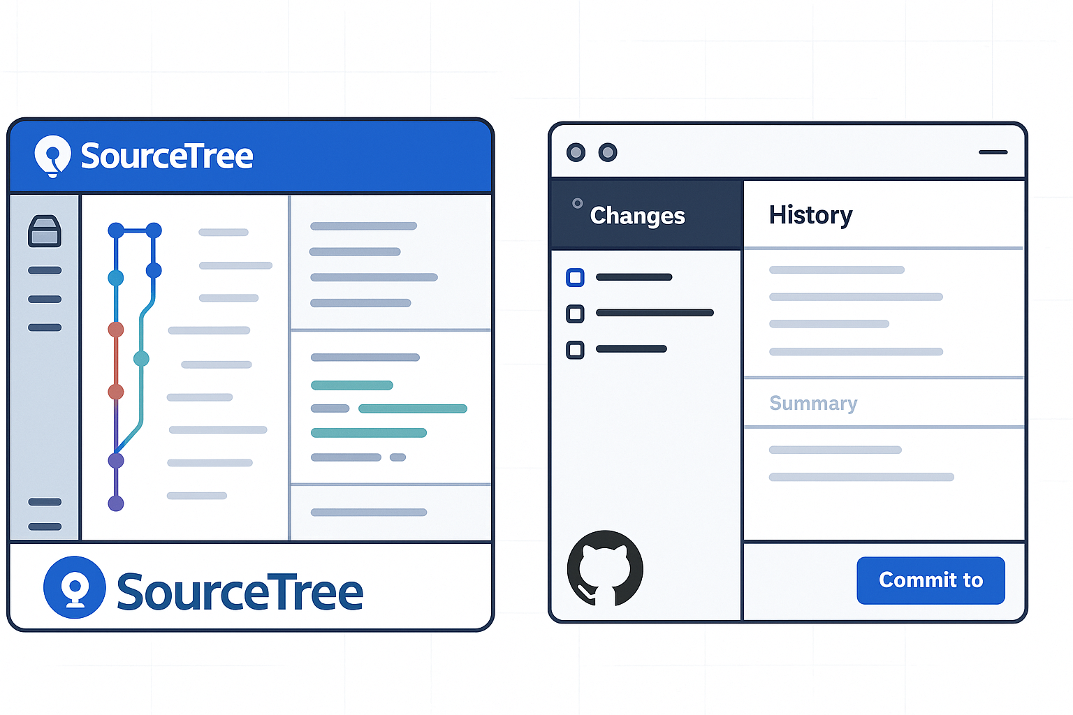
User Interface & Usability
- Sourcetree uses a multi-pane layout:
- Left sidebar: repository tree, branches, tags.
- Top pane: commit history graph.
- Bottom pane: file diffs and staging.
- Pros: Power users can access every Git feature without the CLI.
- Cons: Can feel overwhelming; panels can be crowded.
- GitHub Desktop opts for simplicity:
- Two-column layout: changes on left, history on right.
- One-click actions: clone, fetch, pull, push.
- Pros: Intuitive for new Git users.
- Cons: Power-user features require falling back to the command line.
Integrations & Ecosystem
- Sourcetree
- Deep integration with Bitbucket.
- Jira issue-tracker linking (create branches from issues).
- Supports GitLab and GitHub but with fewer guided workflows.
- Custom actions let you hook into CI/CD scripts.
- GitHub Desktop
- Native support for GitHub.com and GitHub Enterprise.
- Automatically fetches pull requests and issues.
- One-click opening of the repository in GitHub.com UI.
- No first-class Bitbucket/GitLab support.
Performance & Resource Usage
- Sourcetree
- Tends to consume more RAM (200–400 MB idle).
- Can slow down on repositories with large histories or many submodules.
- GitHub Desktop
- Leaner footprint (~100 MB idle).
- Faster launch and repo-scan times on typical projects.
Pros & Cons
Sourcetree
Pros:
- Rich feature set for advanced Git operations.
- Interactive rebase via GUI.
- Extensive integration with Atlassian tools.
Cons:
- Steeper learning curve.
- Heavier on resources.
- UI can be cluttered.
GitHub Desktop
Pros:
- Clean, minimal UI—great for Git newcomers.
- Seamless GitHub integration.
- Lightweight and responsive.
Cons:
- Lacks advanced Git workflows (e.g., Git Flow).
- Limited per-file staging.
- Submodules and custom hooks require CLI.
Conclusion
Choose Sourcetree if you:
- Rely heavily on Bitbucket/Jira.
- Need advanced Git features in a GUI (rebasing, hooks, flows).
- Don’t mind a steeper UI.
Choose GitHub Desktop if you:
- Work primarily with GitHub.com or GitHub Enterprise.
- Want a lightweight, beginner-friendly client.
- Prefer simplicity over feature depth.
Links & Resources
- Sourcetree: https://www.sourcetreeapp.com/
- Sourcetree Documentation: https://confluence.atlassian.com/get-started-with-sourcetree
- GitHub Desktop: https://desktop.github.com/
- GitHub Desktop Docs: https://docs.github.com/desktop
- Sourcetree
-
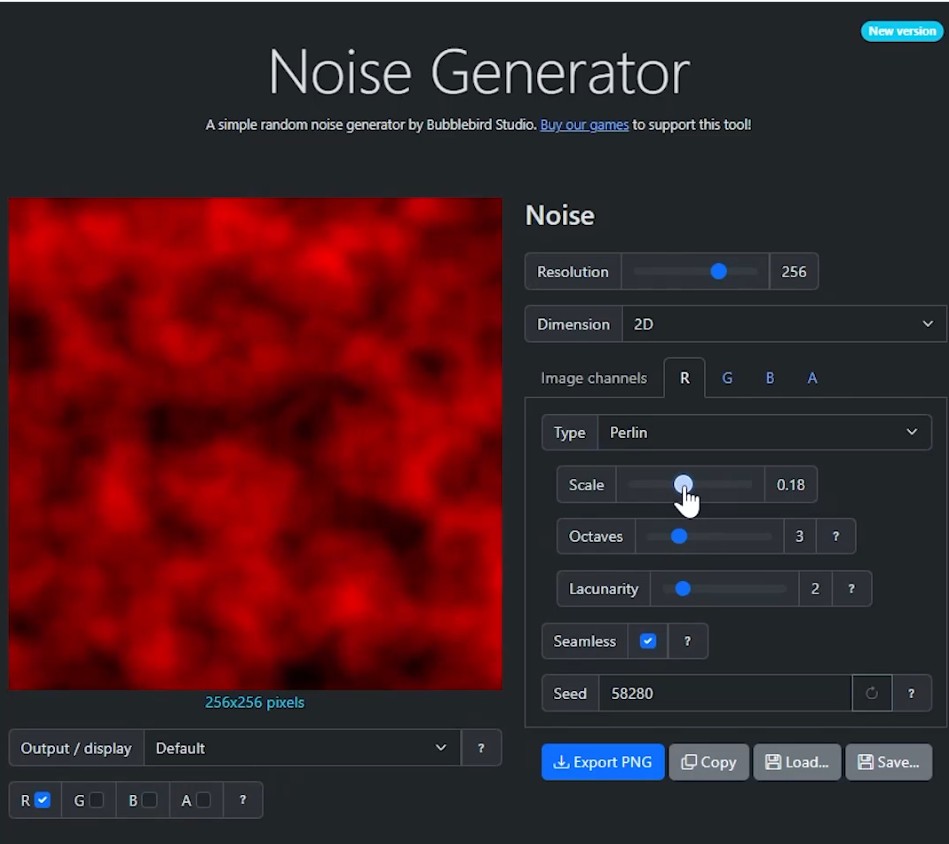
Bubblebird-Studio – Free NoiseGenerator
https://github.com/Bubblebird-Studio/NoiseGenerator
It currently support the following noise models:
Support for Blue Noise is planned.
You can freely use it here: https://noisegen.bubblebirdstudio.com/
-
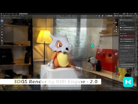
Free 3DGS Render Addon for Blender 2.0
https://superhivemarket.com/products/3dgs-render-by-kiri-engine
https://github.com/Kiri-Innovation/3dgs-render-blender-addon
https://www.kiriengine.app/blender-addon/3dgs-render
The addon is a full 3DGS editing and rendering suite for Blender.3DGS scans can be created from .OBJ files, or 3DGS .PLY files can be imported as mesh objects, offering two distinct workflows. The created objects can be manipulated, animated and rendered inside Blender. Or Blender can be used as an intermediate editing and painting software – with the results being exportable to other 3DGS software and viewers.
-
Unwrella Connect – A Free UV-Packer-IO Bridge for Blender
Homepage: https://www.uv-packer.com/
Download: https://www.uv-packer.com/blender/
Documentation: https://docs.3d-plugin.com/https://docs.3d-plugin.com/unwrellaconnect-blender
UnwrellaConnect for Blender is an extension that seamlessly connects Blender to our standalone UV editing applications, allowing you to run their powerful functionality directly from within the Blender interface – no need to leave your workflow.


COLLECTIONS
| Featured AI
| Design And Composition
| Explore posts
POPULAR SEARCHES
unreal | pipeline | virtual production | free | learn | photoshop | 360 | macro | google | nvidia | resolution | open source | hdri | real-time | photography basics | nuke
FEATURED POSTS
-
Google – Artificial Intelligence free courses
-
Alejandro Villabón and Rafał Kaniewski – Recover Highlights With 8-Bit to High Dynamic Range Half Float Copycat – Nuke
-
copypastecharacter.com – alphabets, special characters, alt codes and symbols library
-
Matt Hallett – WAN 2.1 VACE Total Video Control in ComfyUI
-
NVidia – High-Fidelity 3D Mesh Generation at Scale with Meshtron
-
N8N.io – From Zero to Your First AI Agent in 25 Minutes
-
Gamma correction
-
SourceTree vs Github Desktop – Which one to use
Social Links
DISCLAIMER – Links and images on this website may be protected by the respective owners’ copyright. All data submitted by users through this site shall be treated as freely available to share.
