


BREAKING NEWS
LATEST POSTS
-
Creality K1 Max Review – Large High Speed 3D Printer
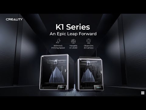
- 300mm x 300mm x 300mm Build Volume
- Compatible Printing Materials Up to 300°C
- Quality of Life Features Like Hands-Free Auto Bed Leveling
- High-Speed CoreXY with 20000 mm/s² Acceleration
- Sturdy Unibody Die-cast Frame
- Assembled & Calibrated Out of the Box
- Max Print Speed: 600mm/s
- Average Print Speed: 300mm/s
- Print Acceleration: 20,000mm/s2
- 32mm³/s Max Flow Hotend
- G-sensor compensates for ringing
- Unibody die-cast frame adds stability
- Reduced Z-banding with upgraded Z-axis
- 0.6mm and 0.8mm sizes (compatible)
- Nozzle Diameter 0.4mm (included)
- Material Types: PLA, ABS, PETG, PET, TPU, PA, ABS, ASA, PC,
PLA-CF*, PA-CF*, PET-CF*
-
Intel Open Image open source Denoiser
Intel Open Image Denoise is an open source library of high-performance, high-quality denoising filters for images rendered with ray tracing. Intel Open Image Denoise is part of the Intel® oneAPI Rendering Toolkit and is released under the permissive Apache 2.0 license.
The purpose of Intel Open Image Denoise is to provide an open, high-quality, efficient, and easy-to-use denoising library that allows one to significantly reduce rendering times in ray tracing based rendering applications. It filters out the Monte Carlo noise inherent to stochastic ray tracing methods like path tracing, reducing the amount of necessary samples per pixel by even multiple orders of magnitude (depending on the desired closeness to the ground truth). A simple but flexible C/C++ API ensures that the library can be easily integrated into most existing or new rendering solutions.
At the heart of the Intel Open Image Denoise library is a collection of efficient deep learning based denoising filters, which were trained to handle a wide range of samples per pixel (spp), from 1 spp to almost fully converged. Thus it is suitable for both preview and final-frame rendering. The filters can denoise images either using only the noisy color (beauty) buffer, or, to preserve as much detail as possible, can optionally utilize auxiliary feature buffers as well (e.g. albedo, normal). Such buffers are supported by most renderers as arbitrary output variables (AOVs) or can be usually implemented with little effort.
-
Tom Hanks on his debut novel “The Making of Another Major Motion Picture Masterpiece”: Nothing comes easy if you learnt all through mistakes…
https://www.cbc.ca/listen/live-radio/1-50-q/clip/16014382-tom-hanks
Two-time Oscar winner Tom Hanks (Forrest Gump, Philadelphia, A League of Their Own) on his debut novel “The Making of Another Major Motion Picture Masterpiece,” the insecurities he’s felt throughout his career, and what drives his passion for filmmaking when it feels like “the odds are stacked against you.”
Nothing comes easy if you learnt all through mistakes…
-
Epic is changing Unreal Engine’s pricing for non-game developers
The change will happen sometime next year and will charge some users on a per-seat model, similar to Photoshop pricing.
Game developers using Unreal Engine won’t be affected and will continue to pay for a license based on a royalty model. However, users in industries like film or automotive will be moved to per-seat pricing, meaning they’ll be charged for the subscription the same way someone might pay for Photoshop.
https://www.theverge.com/2023/10/5/23905082/epic-unreal-engine-pricing-change-film-automotive


FEATURED POSTS


-
Paul Debevec, Chloe LeGendre, Lukas Lepicovsky – Jointly Optimizing Color Rendition and In-Camera Backgrounds in an RGB Virtual Production Stage
https://arxiv.org/pdf/2205.12403.pdf
RGB LEDs vs RGBWP (RGB + lime + phospor converted amber) LEDs
Local copy:


-
What’s the Difference Between Ray Casting, Ray Tracing, Path Tracing and Rasterization? Physical light tracing…
RASTERIZATION
Rasterisation (or rasterization) is the task of taking the information described in a vector graphics format OR the vertices of triangles making 3D shapes and converting them into a raster image (a series of pixels, dots or lines, which, when displayed together, create the image which was represented via shapes), or in other words “rasterizing” vectors or 3D models onto a 2D plane for display on a computer screen.For each triangle of a 3D shape, you project the corners of the triangle on the virtual screen with some math (projective geometry). Then you have the position of the 3 corners of the triangle on the pixel screen. Those 3 points have texture coordinates, so you know where in the texture are the 3 corners. The cost is proportional to the number of triangles, and is only a little bit affected by the screen resolution.
In computer graphics, a raster graphics or bitmap image is a dot matrix data structure that represents a generally rectangular grid of pixels (points of color), viewable via a monitor, paper, or other display medium.
With rasterization, objects on the screen are created from a mesh of virtual triangles, or polygons, that create 3D models of objects. A lot of information is associated with each vertex, including its position in space, as well as information about color, texture and its “normal,” which is used to determine the way the surface of an object is facing.
Computers then convert the triangles of the 3D models into pixels, or dots, on a 2D screen. Each pixel can be assigned an initial color value from the data stored in the triangle vertices.
Further pixel processing or “shading,” including changing pixel color based on how lights in the scene hit the pixel, and applying one or more textures to the pixel, combine to generate the final color applied to a pixel.
The main advantage of rasterization is its speed. However, rasterization is simply the process of computing the mapping from scene geometry to pixels and does not prescribe a particular way to compute the color of those pixels. So it cannot take shading, especially the physical light, into account and it cannot promise to get a photorealistic output. That’s a big limitation of rasterization.
There are also multiple problems:
If you have two triangles one is behind the other, you will draw twice all the pixels. you only keep the pixel from the triangle that is closer to you (Z-buffer), but you still do the work twice.
The borders of your triangles are jagged as it is hard to know if a pixel is in the triangle or out. You can do some smoothing on those, that is anti-aliasing.
You have to handle every triangles (including the ones behind you) and then see that they do not touch the screen at all. (we have techniques to mitigate this where we only look at triangles that are in the field of view)
Transparency is hard to handle (you can’t just do an average of the color of overlapping transparent triangles, you have to do it in the right order)


RAY CASTING
It is almost the exact reverse of rasterization: you start from the virtual screen instead of the vector or 3D shapes, and you project a ray, starting from each pixel of the screen, until it intersect with a triangle.The cost is directly correlated to the number of pixels in the screen and you need a really cheap way of finding the first triangle that intersect a ray. In the end, it is more expensive than rasterization but it will, by design, ignore the triangles that are out of the field of view.
You can use it to continue after the first triangle it hit, to take a little bit of the color of the next one, etc… This is useful to handle the border of the triangle cleanly (less jagged) and to handle transparency correctly.
RAYTRACING


Same idea as ray casting except once you hit a triangle you reflect on it and go into a different direction. The number of reflection you allow is the “depth” of your ray tracing. The color of the pixel can be calculated, based off the light source and all the polygons it had to reflect off of to get to that screen pixel.The easiest way to think of ray tracing is to look around you, right now. The objects you’re seeing are illuminated by beams of light. Now turn that around and follow the path of those beams backwards from your eye to the objects that light interacts with. That’s ray tracing.
Ray tracing is eye-oriented process that needs walking through each pixel looking for what object should be shown there, which is also can be described as a technique that follows a beam of light (in pixels) from a set point and simulates how it reacts when it encounters objects.
Compared with rasterization, ray tracing is hard to be implemented in real time, since even one ray can be traced and processed without much trouble, but after one ray bounces off an object, it can turn into 10 rays, and those 10 can turn into 100, 1000…The increase is exponential, and the the calculation for all these rays will be time consuming.
Historically, computer hardware hasn’t been fast enough to use these techniques in real time, such as in video games. Moviemakers can take as long as they like to render a single frame, so they do it offline in render farms. Video games have only a fraction of a second. As a result, most real-time graphics rely on the another technique called rasterization.

PATH TRACING
Path tracing can be used to solve more complex lighting situations.
Path tracing is a type of ray tracing. When using path tracing for rendering, the rays only produce a single ray per bounce. The rays do not follow a defined line per bounce (to a light, for example), but rather shoot off in a random direction. The path tracing algorithm then takes a random sampling of all of the rays to create the final image. This results in sampling a variety of different types of lighting.When a ray hits a surface it doesn’t trace a path to every light source, instead it bounces the ray off the surface and keeps bouncing it until it hits a light source or exhausts some bounce limit.
It then calculates the amount of light transferred all the way to the pixel, including any color information gathered from surfaces along the way.
It then averages out the values calculated from all the paths that were traced into the scene to get the final pixel color value.It requires a ton of computing power and if you don’t send out enough rays per pixel or don’t trace the paths far enough into the scene then you end up with a very spotty image as many pixels fail to find any light sources from their rays. So when you increase the the samples per pixel, you can see the image quality becomes better and better.
Ray tracing tends to be more efficient than path tracing. Basically, the render time of a ray tracer depends on the number of polygons in the scene. The more polygons you have, the longer it will take.
Meanwhile, the rendering time of a path tracer can be indifferent to the number of polygons, but it is related to light situation: If you add a light, transparency, translucence, or other shader effects, the path tracer will slow down considerably.
blogs.nvidia.com/blog/2018/03/19/whats-difference-between-ray-tracing-rasterization/
https://en.wikipedia.org/wiki/Rasterisation
https://www.quora.com/Whats-the-difference-between-ray-tracing-and-path-tracing