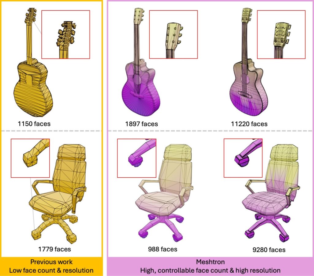
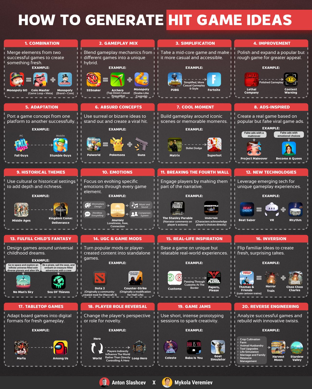
Meshtron provides a simple and scalable, data-driven solution for generating intricate, artist-like meshes of up to 64K faces at 1024-level coordinate resolution. This is over an order of magnitude higher face count and 8x higher coordinate resolution compared to existing methods.
A model that can generate the next frame of a 3D scene based on the previous frame(s) and user input, trained on video data, and running in real-time.
World models enable AI systems to simulate and reason about their environments, pushing forward autonomous decision-making and real-world problem-solving.
The key insight is that by training on video data, these models learn not just how to generate images, but also:
the physics of our world (objects fall down, water flows, etc)
how objects look from different angles (that chair should look the same as you walk around it)
how things move and interact (a ball bouncing off a wall, a character walking on sand)
basic spatial understanding (you can’t walk through walls)
Some companies, like World Labs, are taking a hybrid approach: using World Models to generate static 3D representations that can then be rendered using traditional 3D engines (in this case, Gaussian Splatting). This gives you the best of both worlds: the creative power of AI generation with the multiview consistency and performance of traditional rendering.
QuickTime (.mov) files are fundamentally time-based, not frame-based, and so don’t have a built-in, uniform “first frame/last frame” field you can set as numeric frame IDs. Instead, tools like Shotgun Create rely on the timecode track and the movie’s duration to infer frame numbers. If you want Shotgun to pick up a non-default frame range (e.g. start at 1001, end at 1064), you must bake in an SMPTE timecode that corresponds to your desired start frame, and ensure the movie’s duration matches your clip length.
How Shotgun Reads Frame Ranges
Default start frame is 1. If no timecode metadata is present, Shotgun assumes the movie begins at frame 1.
Timecode ⇒ frame number. Shotgun Create “honors the timecodes of media sources,” mapping the embedded TC to frame IDs. For example, a 24 fps QuickTime tagged with a start timecode of 00:00:41:17 will be interpreted as beginning on frame 1001 (1001 ÷ 24 fps ≈ 41.71 s).
Embedding a Start Timecode
QuickTime uses a tmcd (timecode) track. You can bake in an SMPTE track via FFmpeg’s -timecode flag or via Compressor/encoder settings:
Compute your start TC.
Desired start frame = 1001
Frame 1001 at 24 fps ⇒ 1001 ÷ 24 ≈ 41.708 s ⇒ TC 00:00:41:17
RASTERIZATION Rasterisation (or rasterization) is the task of taking the information described in a vector graphics format OR the vertices of triangles making 3D shapes and converting them into a raster image (a series of pixels, dots or lines, which, when displayed together, create the image which was represented via shapes), or in other words “rasterizing” vectors or 3D models onto a 2D plane for display on a computer screen.
For each triangle of a 3D shape, you project the corners of the triangle on the virtual screen with some math (projective geometry). Then you have the position of the 3 corners of the triangle on the pixel screen. Those 3 points have texture coordinates, so you know where in the texture are the 3 corners. The cost is proportional to the number of triangles, and is only a little bit affected by the screen resolution.
In computer graphics, a raster graphics orbitmap image is a dot matrix data structure that represents a generally rectangular grid of pixels (points of color), viewable via a monitor, paper, or other display medium.
With rasterization, objects on the screen are created from a mesh of virtual triangles, or polygons, that create 3D models of objects. A lot of information is associated with each vertex, including its position in space, as well as information about color, texture and its “normal,” which is used to determine the way the surface of an object is facing.
Computers then convert the triangles of the 3D models into pixels, or dots, on a 2D screen. Each pixel can be assigned an initial color value from the data stored in the triangle vertices.
Further pixel processing or “shading,” including changing pixel color based on how lights in the scene hit the pixel, and applying one or more textures to the pixel, combine to generate the final color applied to a pixel.
The main advantage of rasterization is its speed. However, rasterization is simply the process of computing the mapping from scene geometry to pixels and does not prescribe a particular way to compute the color of those pixels. So it cannot take shading, especially the physical light, into account and it cannot promise to get a photorealistic output. That’s a big limitation of rasterization.
There are also multiple problems:
If you have two triangles one is behind the other, you will draw twice all the pixels. you only keep the pixel from the triangle that is closer to you (Z-buffer), but you still do the work twice.
The borders of your triangles are jagged as it is hard to know if a pixel is in the triangle or out. You can do some smoothing on those, that is anti-aliasing.
You have to handle every triangles (including the ones behind you) and then see that they do not touch the screen at all. (we have techniques to mitigate this where we only look at triangles that are in the field of view)
Transparency is hard to handle (you can’t just do an average of the color of overlapping transparent triangles, you have to do it in the right order)