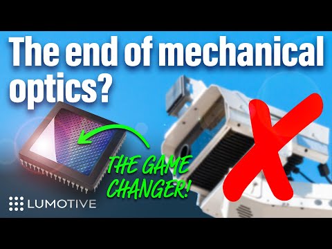
Programmable Optics for LiDAR and 3D Sensing: How Lumotive’s LCM is Changing the Game
For decades, LiDAR and 3D sensing systems have relied on mechanical mirrors and bulky optics to direct light and measure distance. But at CES 2025, Lumotive unveiled a breakthrough—a semiconductor-based programmable optic that removes the need for moving parts altogether.
The Problem with Traditional LiDAR and Optical Systems
LiDAR and 3D sensing systems work by sending out light and measuring when it returns, creating a precise depth map of the environment. However, traditional systems have relied on physically moving mirrors and lenses, which introduce several limitations:
Size and weight – Bulky components make integration difficult.
Complexity – Mechanical parts are prone to failure and expensive to produce.
Speed limitations – Physical movement slows down scanning and responsiveness.
To bring high-resolution depth sensing to wearables, smart devices, and autonomous systems, a new approach is needed.
Enter the Light Control Metasurface (LCM)
Lumotive’s Light Control Metasurface (LCM) replaces mechanical mirrors with a semiconductor-based optical chip. This allows LiDAR and 3D sensing systems to steer light electronically, just like a processor manages data. The advantages are game-changing:
No moving parts – Increased durability and reliability
Ultra-compact form factor – Fits into small devices and wearables
Real-time reconfigurability – Optics can adapt instantly to changing environments
Energy-efficient scanning – Focuses on relevant areas, saving power
How Does it Work?
LCM technology works by controlling how light is directed using programmable metasurfaces. Unlike traditional optics that require physical movement, Lumotive’s approach enables light to be redirected with software-controlled precision.
This means:
No mechanical delays – Everything happens at electronic speeds.
AI-enhanced tracking – The sensor can focus only on relevant objects.
Scalability – The same technology can be adapted for industrial, automotive, AR/VR, and smart city applications.
Live Demo: Real-Time 3D Sensing
At CES 2025, Lumotive showcased how their LCM-enabled sensor can scan a room in real time, creating an instant 3D point cloud. Unlike traditional LiDAR, which has a fixed scan pattern, this system can dynamically adjust to track people, objects, and even gestures on the fly.
This is a huge leap forward for AI-powered perception systems, allowing cameras and sensors to interpret their environment more intelligently than ever before.
Who Needs This Technology?
Lumotive’s programmable optics have the potential to disrupt multiple industries, including:
Automotive – Advanced LiDAR for autonomous vehicles
Industrial automation – Precision 3D scanning for robotics and smart factories
Smart cities – Real-time monitoring of public spaces
AR/VR/XR – Depth-aware tracking for immersive experiences
The Future of 3D Sensing Starts Here
Lumotive’s Light Control Metasurface represents a fundamental shift in how we think about optics and 3D sensing. By bringing programmability to light steering, it opens up new possibilities for faster, smarter, and more efficient depth-sensing technologies.
With traditional LiDAR now facing a serious challenge, the question is: Who will be the first to integrate programmable optics into their designs?
ComfyDock is a tool that allows you to easily manage your ComfyUI environments via Docker.
Common Challenges with ComfyUI
Custom Node Installation Issues: Installing new custom nodes can inadvertently change settings across the whole installation, potentially breaking the environment.
Workflow Compatibility: Workflows are often tested with specific custom nodes and ComfyUI versions. Running these workflows on different setups can lead to errors and frustration.
Security Risks: Installing custom nodes directly on your host machine increases the risk of malicious code execution.
How ComfyDock Helps
Environment Duplication: Easily duplicate your current environment before installing custom nodes. If something breaks, revert to the original environment effortlessly.
Deployment and Sharing: Workflow developers can commit their environments to a Docker image, which can be shared with others and run on cloud GPUs to ensure compatibility.
Enhanced Security: Containers help to isolate the environment, reducing the risk of malicious code impacting your host machine.
Every 11 years the Sun’s magnetic pole flips. Leading up to this event, there is a period of increased solar activity — from sunspots and solar flares to spectacular northern and southern lights. The current solar cycle began in 2019 and scientists predict it will peak sometime in 2024 or 2025 before the Sun returns to a lower level of activity in the early 2030s.
The most dramatic events produced by the solar photosphere (the “surface” of the Sun) are coronal mass ejections. When these occur and solar particles get spewed out into space, they can wash over the Earth and interact with our magnetic field. This interaction funnels the charged particles towards Earth’s own North and South magnetic poles — where the particles interact with molecules in Earth’s ionosphere and cause them to fluoresce — phenomena known as aurora borealis (northern lights) and aurora australis (southern lights).
In 2019, it was predicted that the solar maximum would likely occur sometime around July 2025. However, Nature does not have to conform with our predictions, and seems to be giving us the maximum earlier than expected.
Very strong solar activity — especially the coronal mass ejections — can indeed wreak some havoc on our satellite and communication electronics. Most often, it is fairly minor — we get what is known as a “radio blackout” that interferes with some of our radio communications. Once in a while, though, a major solar event occurs. The last of these was in 1859 in what is now known as the Carrington Event, which knocked out telegraph communications across Europe and North America. Should a similar solar storm happen today it would be fairly devastating, affecting major aspects of our infrastructure including our power grid and, (gasp), the internet itself.
Beyond Technicolor’s specific challenges, the broader VFX industry continues to grapple with systemic issues, including cost-cutting pressures, exploitative working conditions, and an unsustainable business model. VFX houses often operate on razor-thin margins, competing in a race to the bottom due to studios’ demand for cheaper and faster work. This results in a cycle of overwork, burnout, and, in many cases, eventual bankruptcy, as seen with Rhythm & Hues in 2013 and now at Technicolor. The reliance on tax incentives and outsourcing further complicates matters, making VFX work highly unstable. With major vendors collapsing and industry workers facing continued uncertainty, many are calling for structural changes, including better contracts, collective bargaining, and a more sustainable production pipeline. Without meaningful reform, the industry risks seeing more historic names disappear and countless skilled artists move to other fields.
For many modern programming languages, the associated tooling has the lock-file based dependency management mechanism baked in. For a great example, consider Rust’s Cargo.
Not so with Python.
The default package manager for Python is pip. The default instruction to install a package is to run pip install package. Unfortunately, this imperative approach for creating your environment is entirely divorced from the versioning of your code. You very quickly end up in a situation where you have 100’s of packages installed. You no longer know which packages you explicitly asked to install, and which packages got installed because they were a transitive dependency. You no longer know which version of the code worked in which environment, and there is no way to roll back to an earlier version of your environment. Installing any new package could break your environment. …
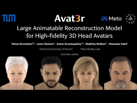
Avat3r takes 4 input images of a person’s face and generates an animatable 3D head avatar in a single forward pass. The resulting 3D head representation can be animated at interactive rates. The entire creation process of the 3D avatar, from taking 4 smartphone pictures to the final result, can be executed within minutes.
The Nemesis system, for those unfamiliar, is a clever in-game mechanic which tracks a player’s actions to create enemies that feel capable of remembering past encounters. In the studio’s Middle-earth games, this allowed foes to rise through the ranks and enact revenge.
The patent itself – which you can view here – was originally filed back in 2016, before it was granted in 2021. It is dubbed “Nemesis characters, nemesis forts, social vendettas and followers in computer games”. As it stands, the patent has an expiration date of 11th August, 2036.
zopieux on Dec 5, 2024 : Ultralytics was attacked (or did it on purpose, waiting for a post mortem there), 8.3.41 contains nefarious code downloading and running a crypto miner hosted as a GitHub blob.
Building a successful business requires a focus on three key elements: product excellence, go-to-market strategy, and operational excellence. Neglecting any of these areas can lead to failure, as evidenced by the high percentage of startups that don’t make it past the five-year mark. Founders and CEOs must ensure a solid product foundation while also integrating effective sales, marketing, and management strategies to achieve sustainable growth and scale.
Foundation: Product Excellence, Core Values and Mission
Core Values: These are the guiding principles that dictate behavior and action within the company. They form the ethical foundation and are crucial for maintaining consistency in decision-making.
Mission: This defines the company’s purpose and goals. A clear and compelling mission helps align the team and provides a sense of direction.
Efficiency and Scalability: This layer focuses on creating efficient processes that can scale as the company grows. Streamlined operations reduce costs and increase productivity.
Structure: Operational Excellence and Innovation
Operational Excellence: Efficient processes, quality control, and continuous improvement fall into this layer. Ensuring that the company operates smoothly and effectively is crucial for sustainability.
Innovation: Staying competitive requires innovation. This involves developing new products, services, or processes that add value and keep the company relevant in the market.
Quality Control and Continuous Improvement: Ensuring that operational processes are of high quality and constantly improving helps maintain product excellence and customer satisfaction.
Technology and Infrastructure: Investing in the right technology and infrastructure to support business operations is vital. This includes everything from manufacturing equipment to software systems that enhance operational efficiency.
Strategy: Go-to-Market Strategy, Vision and Long-Term Planning
Vision: A forward-looking vision inspires and motivates the team. It outlines where the company aims to be in the future and helps in setting long-term goals.
Strategic Planning: This involves setting long-term goals and determining the actions and resources needed to achieve them. It includes market analysis, competitive strategy, and growth planning.
Market Understanding: A deep understanding of the target market, including customer segments, competitors, and market trends, is essential. This knowledge helps in positioning the product effectively.
Marketing and Sales Execution: This involves creating a robust marketing plan that includes branding, messaging, and advertising strategies to attract and retain customers. Additionally, building a strong sales strategy ensures that the product reaches the right customers through the right channels.
Customer Acquisition and Retention: Effective strategies for acquiring new customers and retaining existing ones are critical. This includes loyalty programs, customer service excellence, and engagement initiatives.
3. Generative AI Fundamentals: Earn a skill badge by demonstrating your understanding of foundational concepts in Generative AI. https://www.cloudskillsboost.google/paths
7. Transformer Models and BERT Model: Get a comprehensive introduction to the Transformer architecture and the Bidirectional Encoder Representations from the Transformers (BERT) model. https://www.cloudskillsboost.google/course_templates/538
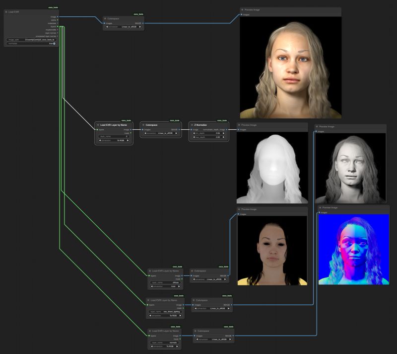
In color technology, color depth also known as bit depth, is either the number of bits used to indicate the color of a single pixel, OR the number of bits used for each color component of a single pixel.
When referring to a pixel, the concept can be defined as bits per pixel (bpp).
When referring to a color component, the concept can be defined as bits per component, bits per channel, bits per color (all three abbreviated bpc), and also bits per pixel component, bits per color channel or bits per sample (bps). Modern standards tend to use bits per component, but historical lower-depth systems used bits per pixel more often.
Color depth is only one aspect of color representation, expressing the precision with which the amount of each primary can be expressed; the other aspect is how broad a range of colors can be expressed (the gamut). The definition of both color precision and gamut is accomplished with a color encoding specification which assigns a digital code value to a location in a color space.
RASTERIZATION Rasterisation (or rasterization) is the task of taking the information described in a vector graphics format OR the vertices of triangles making 3D shapes and converting them into a raster image (a series of pixels, dots or lines, which, when displayed together, create the image which was represented via shapes), or in other words “rasterizing” vectors or 3D models onto a 2D plane for display on a computer screen.
For each triangle of a 3D shape, you project the corners of the triangle on the virtual screen with some math (projective geometry). Then you have the position of the 3 corners of the triangle on the pixel screen. Those 3 points have texture coordinates, so you know where in the texture are the 3 corners. The cost is proportional to the number of triangles, and is only a little bit affected by the screen resolution.
In computer graphics, a raster graphics orbitmap image is a dot matrix data structure that represents a generally rectangular grid of pixels (points of color), viewable via a monitor, paper, or other display medium.
With rasterization, objects on the screen are created from a mesh of virtual triangles, or polygons, that create 3D models of objects. A lot of information is associated with each vertex, including its position in space, as well as information about color, texture and its “normal,” which is used to determine the way the surface of an object is facing.
Computers then convert the triangles of the 3D models into pixels, or dots, on a 2D screen. Each pixel can be assigned an initial color value from the data stored in the triangle vertices.
Further pixel processing or “shading,” including changing pixel color based on how lights in the scene hit the pixel, and applying one or more textures to the pixel, combine to generate the final color applied to a pixel.
The main advantage of rasterization is its speed. However, rasterization is simply the process of computing the mapping from scene geometry to pixels and does not prescribe a particular way to compute the color of those pixels. So it cannot take shading, especially the physical light, into account and it cannot promise to get a photorealistic output. That’s a big limitation of rasterization.
There are also multiple problems:
If you have two triangles one is behind the other, you will draw twice all the pixels. you only keep the pixel from the triangle that is closer to you (Z-buffer), but you still do the work twice.
The borders of your triangles are jagged as it is hard to know if a pixel is in the triangle or out. You can do some smoothing on those, that is anti-aliasing.
You have to handle every triangles (including the ones behind you) and then see that they do not touch the screen at all. (we have techniques to mitigate this where we only look at triangles that are in the field of view)
Transparency is hard to handle (you can’t just do an average of the color of overlapping transparent triangles, you have to do it in the right order)
RAY CASTING It is almost the exact reverse of rasterization: you start from the virtual screen instead of the vector or 3D shapes, and you project a ray, starting from each pixel of the screen, until it intersect with a triangle.
The cost is directly correlated to the number of pixels in the screen and you need a really cheap way of finding the first triangle that intersect a ray. In the end, it is more expensive than rasterization but it will, by design, ignore the triangles that are out of the field of view.
You can use it to continue after the first triangle it hit, to take a little bit of the color of the next one, etc… This is useful to handle the border of the triangle cleanly (less jagged) and to handle transparency correctly.
RAYTRACING
Same idea as ray casting except once you hit a triangle you reflect on it and go into a different direction. The number of reflection you allow is the “depth” of your ray tracing. The color of the pixel can be calculated, based off the light source and all the polygons it had to reflect off of to get to that screen pixel.
The easiest way to think of ray tracing is to look around you, right now. The objects you’re seeing are illuminated by beams of light. Now turn that around and follow the path of those beams backwards from your eye to the objects that light interacts with. That’s ray tracing.
Ray tracing is eye-oriented process that needs walking through each pixel looking for what object should be shown there, which is also can be described as a technique that follows a beam of light (in pixels) from a set point and simulates how it reacts when it encounters objects.
Compared with rasterization, ray tracing is hard to be implemented in real time, since even one ray can be traced and processed without much trouble, but after one ray bounces off an object, it can turn into 10 rays, and those 10 can turn into 100, 1000…The increase is exponential, and the the calculation for all these rays will be time consuming.
Historically, computer hardware hasn’t been fast enough to use these techniques in real time, such as in video games. Moviemakers can take as long as they like to render a single frame, so they do it offline in render farms. Video games have only a fraction of a second. As a result, most real-time graphics rely on the another technique called rasterization.
PATH TRACING Path tracing can be used to solve more complex lighting situations. Path tracing is a type of ray tracing. When using path tracing for rendering, the rays only produce a single ray per bounce. The rays do not follow a defined line per bounce(to a light, for example), but rather shoot off in a random direction. The path tracing algorithm then takes a random sampling of all of the rays to create the final image. This results in sampling a variety of different types of lighting.
When a ray hits a surface it doesn’t trace a path to every light source, instead it bounces the ray off the surface and keeps bouncing it until it hits a light source or exhausts some bounce limit. It then calculates the amount of light transferred all the way to the pixel, including any color information gathered from surfaces along the way. It then averages out the values calculated from all the paths that were traced into the scene to get the final pixel color value.
It requires a ton of computing power and if you don’t send out enough rays per pixel or don’t trace the paths far enough into the scene then you end up with a very spotty image as many pixels fail to find any light sources from their rays. So when you increase the the samples per pixel, you can see the image quality becomes better and better.
Ray tracing tends to be more efficient than path tracing. Basically, the render time of a ray tracer depends on the number of polygons in the scene. The more polygons you have, the longer it will take. Meanwhile, the rendering time of a path tracer can be indifferent to the number of polygons, but it is related to light situation: If you add a light, transparency, translucence, or other shader effects, the path tracer will slow down considerably.