


BREAKING NEWS
LATEST POSTS
-
Micro LED displays
Micro LED displays are a cutting-edge technology that promise significant improvements over existing display methods like OLED and LCD. By using tiny, individual LEDs for each pixel, these displays can deliver exceptional brightness, contrast, and energy efficiency. Their inherent durability and superior performance make them an attractive option for high-end consumer electronics, wearable devices, and even large-scale display panels.
The technology is seen as the future of display innovation, aiming to merge high-quality visuals with low power consumption and long-lasting performance.Despite their advantages, micro LED displays face substantial manufacturing hurdles that have slowed their mass-market adoption. The production process requires the precise transfer and alignment of millions of microscopic LEDs onto a substrate—a task that is both technically challenging and cost-intensive. Issues with yield, scalability, and quality control continue to persist, making it difficult to achieve the economies of scale necessary for widespread commercial use. As industry leaders invest heavily in research and development to overcome these obstacles, the technology remains on the cusp of becoming a viable alternative to current display technologies.

-
Nvidia CUDA Toolkit – a development environment for creating high-performance, GPU-accelerated applications
https://developer.nvidia.com/cuda-toolkit
With it, you can develop, optimize, and deploy your applications on GPU-accelerated embedded systems, desktop workstations, enterprise data centers, cloud-based platforms, and supercomputers. The toolkit includes GPU-accelerated libraries, debugging and optimization tools, a C/C++ compiler, and a runtime library.
https://www.youtube.com/watch?v=-P28LKWTzrI

Check your Cuda version, it will be the release version here:
>>> nvcc --version
nvcc: NVIDIA (R) Cuda compiler driver
Copyright (c) 2005-2024 NVIDIA Corporation
Built on Wed_Apr_17_19:36:51_Pacific_Daylight_Time_2024
Cuda compilation tools, release 12.5, V12.5.40
Build cuda_12.5.r12.5/compiler.34177558_0
or from here:
>>> nvidia-smi Mon Jun 16 12:35:20 2025 +-----------------------------------------------------------------------------------------+ | NVIDIA-SMI 555.85 Driver Version: 555.85 CUDA Version: 12.5 | |-----------------------------------------+------------------------+----------------------+ -
HumanDiT – Pose-Guided Diffusion Transformer for Long-form Human Motion Video Generation
https://agnjason.github.io/HumanDiT-page
By inputting a single character image and template pose video, our method can generate vocal avatar videos featuring not only pose-accurate rendering but also realistic body shapes.
-
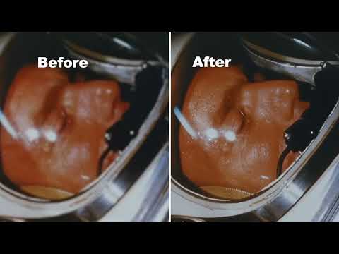
DynVFX – Augmenting Real Videoswith Dynamic Content
Given an input video and a simple user-provided text instruction describing the desired content, our method synthesizes dynamic objects or complex scene effects that naturally interact with the existing scene over time. The position, appearance, and motion of the new content are seamlessly integrated into the original footage while accounting for camera motion, occlusions, and interactions with other dynamic objects in the scene, resulting in a cohesive and realistic output video.
https://dynvfx.github.io/sm/index.html


FEATURED POSTS


-
What’s the Difference Between Ray Casting, Ray Tracing, Path Tracing and Rasterization? Physical light tracing…
RASTERIZATION
Rasterisation (or rasterization) is the task of taking the information described in a vector graphics format OR the vertices of triangles making 3D shapes and converting them into a raster image (a series of pixels, dots or lines, which, when displayed together, create the image which was represented via shapes), or in other words “rasterizing” vectors or 3D models onto a 2D plane for display on a computer screen.For each triangle of a 3D shape, you project the corners of the triangle on the virtual screen with some math (projective geometry). Then you have the position of the 3 corners of the triangle on the pixel screen. Those 3 points have texture coordinates, so you know where in the texture are the 3 corners. The cost is proportional to the number of triangles, and is only a little bit affected by the screen resolution.
In computer graphics, a raster graphics or bitmap image is a dot matrix data structure that represents a generally rectangular grid of pixels (points of color), viewable via a monitor, paper, or other display medium.
With rasterization, objects on the screen are created from a mesh of virtual triangles, or polygons, that create 3D models of objects. A lot of information is associated with each vertex, including its position in space, as well as information about color, texture and its “normal,” which is used to determine the way the surface of an object is facing.
Computers then convert the triangles of the 3D models into pixels, or dots, on a 2D screen. Each pixel can be assigned an initial color value from the data stored in the triangle vertices.
Further pixel processing or “shading,” including changing pixel color based on how lights in the scene hit the pixel, and applying one or more textures to the pixel, combine to generate the final color applied to a pixel.
The main advantage of rasterization is its speed. However, rasterization is simply the process of computing the mapping from scene geometry to pixels and does not prescribe a particular way to compute the color of those pixels. So it cannot take shading, especially the physical light, into account and it cannot promise to get a photorealistic output. That’s a big limitation of rasterization.
There are also multiple problems:
If you have two triangles one is behind the other, you will draw twice all the pixels. you only keep the pixel from the triangle that is closer to you (Z-buffer), but you still do the work twice.
The borders of your triangles are jagged as it is hard to know if a pixel is in the triangle or out. You can do some smoothing on those, that is anti-aliasing.
You have to handle every triangles (including the ones behind you) and then see that they do not touch the screen at all. (we have techniques to mitigate this where we only look at triangles that are in the field of view)
Transparency is hard to handle (you can’t just do an average of the color of overlapping transparent triangles, you have to do it in the right order)


RAY CASTING
It is almost the exact reverse of rasterization: you start from the virtual screen instead of the vector or 3D shapes, and you project a ray, starting from each pixel of the screen, until it intersect with a triangle.The cost is directly correlated to the number of pixels in the screen and you need a really cheap way of finding the first triangle that intersect a ray. In the end, it is more expensive than rasterization but it will, by design, ignore the triangles that are out of the field of view.
You can use it to continue after the first triangle it hit, to take a little bit of the color of the next one, etc… This is useful to handle the border of the triangle cleanly (less jagged) and to handle transparency correctly.
RAYTRACING


Same idea as ray casting except once you hit a triangle you reflect on it and go into a different direction. The number of reflection you allow is the “depth” of your ray tracing. The color of the pixel can be calculated, based off the light source and all the polygons it had to reflect off of to get to that screen pixel.The easiest way to think of ray tracing is to look around you, right now. The objects you’re seeing are illuminated by beams of light. Now turn that around and follow the path of those beams backwards from your eye to the objects that light interacts with. That’s ray tracing.
Ray tracing is eye-oriented process that needs walking through each pixel looking for what object should be shown there, which is also can be described as a technique that follows a beam of light (in pixels) from a set point and simulates how it reacts when it encounters objects.
Compared with rasterization, ray tracing is hard to be implemented in real time, since even one ray can be traced and processed without much trouble, but after one ray bounces off an object, it can turn into 10 rays, and those 10 can turn into 100, 1000…The increase is exponential, and the the calculation for all these rays will be time consuming.
Historically, computer hardware hasn’t been fast enough to use these techniques in real time, such as in video games. Moviemakers can take as long as they like to render a single frame, so they do it offline in render farms. Video games have only a fraction of a second. As a result, most real-time graphics rely on the another technique called rasterization.

PATH TRACING
Path tracing can be used to solve more complex lighting situations.
Path tracing is a type of ray tracing. When using path tracing for rendering, the rays only produce a single ray per bounce. The rays do not follow a defined line per bounce (to a light, for example), but rather shoot off in a random direction. The path tracing algorithm then takes a random sampling of all of the rays to create the final image. This results in sampling a variety of different types of lighting.When a ray hits a surface it doesn’t trace a path to every light source, instead it bounces the ray off the surface and keeps bouncing it until it hits a light source or exhausts some bounce limit.
It then calculates the amount of light transferred all the way to the pixel, including any color information gathered from surfaces along the way.
It then averages out the values calculated from all the paths that were traced into the scene to get the final pixel color value.It requires a ton of computing power and if you don’t send out enough rays per pixel or don’t trace the paths far enough into the scene then you end up with a very spotty image as many pixels fail to find any light sources from their rays. So when you increase the the samples per pixel, you can see the image quality becomes better and better.
Ray tracing tends to be more efficient than path tracing. Basically, the render time of a ray tracer depends on the number of polygons in the scene. The more polygons you have, the longer it will take.
Meanwhile, the rendering time of a path tracer can be indifferent to the number of polygons, but it is related to light situation: If you add a light, transparency, translucence, or other shader effects, the path tracer will slow down considerably.
blogs.nvidia.com/blog/2018/03/19/whats-difference-between-ray-tracing-rasterization/
https://en.wikipedia.org/wiki/Rasterisation
https://www.quora.com/Whats-the-difference-between-ray-tracing-and-path-tracing


