


BREAKING NEWS
LATEST POSTS
-
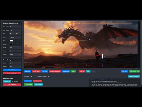
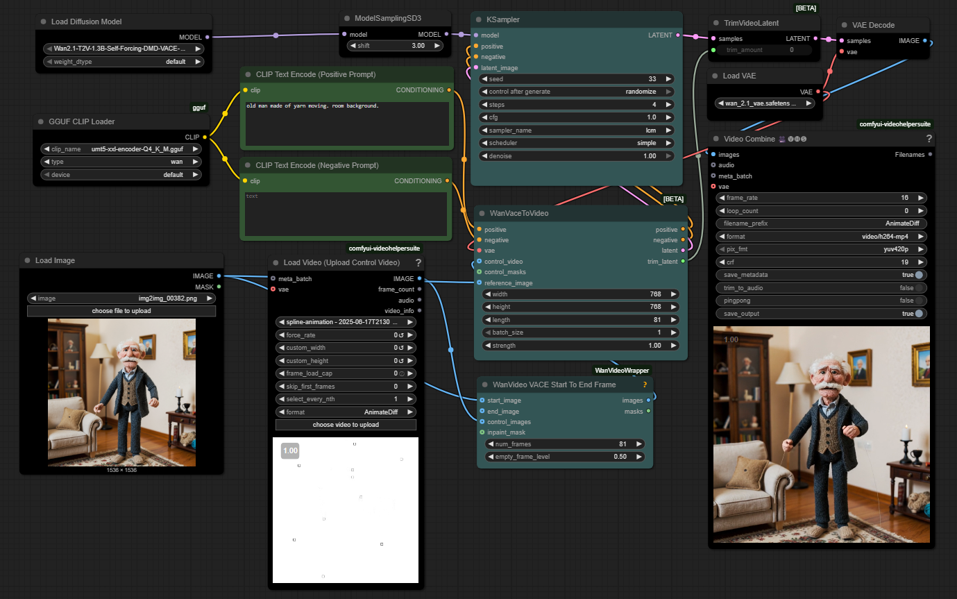
WhatDreamsCost Spline-Path-Control – Create motion controls for ComfyUI
https://github.com/WhatDreamsCost/Spline-Path-Control
https://whatdreamscost.github.io/Spline-Path-Control/
https://github.com/WhatDreamsCost/Spline-Path-Control/tree/main/example_workflows
Spline Path Control is a simple tool designed to make it easy to create motion controls. It allows you to create and animate shapes that follow splines, and then export the result as a
.webmvideo file.
This project was created to simplify the process of generating control videos for tools like VACE. Use it to control the motion of anything (camera movement, objects, humans etc) all without extra prompting.- Multi-Spline Editing: Create multiple, independent spline paths
- Easy To Use Controls: Quickly edit splines and points
- Full Control of Splines and Shapes:
- Start Frame: Set a delay before a spline’s animation begins.
- Duration: Control the speed of the shape along its path.
- Easing: Apply
Linear,Ease-in,Ease-out, andEase-in-outfunctions for smooth acceleration and deceleration. - Tension: Adjust the “curviness” of the spline path.
- Shape Customization: Change the shape (circle, square, triangle), size, fill color, and border.
- Reference Images: Drag and drop or upload a background image to trace paths over an existing image.
- WebM Export: Export your animation with a white background, perfect for use as a control video in VACE.
-
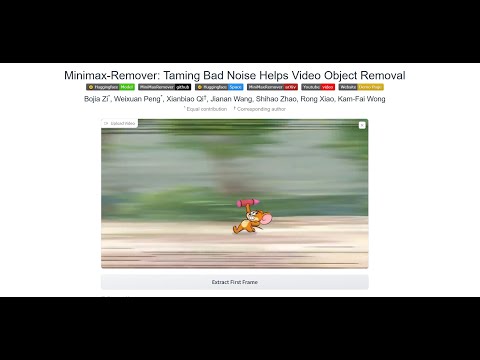
MiniMax-Remover – Taming Bad Noise Helps Video Object Removal Rotoscoping
https://github.com/zibojia/MiniMax-Remover
MiniMax-Remover is a fast and effective video object remover based on minimax optimization. It operates in two stages: the first stage trains a remover using a simplified DiT architecture, while the second stage distills a robust remover with CFG removal and fewer inference steps.


FEATURED POSTS

-
What’s the Difference Between Ray Casting, Ray Tracing, Path Tracing and Rasterization? Physical light tracing…
RASTERIZATION
Rasterisation (or rasterization) is the task of taking the information described in a vector graphics format OR the vertices of triangles making 3D shapes and converting them into a raster image (a series of pixels, dots or lines, which, when displayed together, create the image which was represented via shapes), or in other words “rasterizing” vectors or 3D models onto a 2D plane for display on a computer screen.For each triangle of a 3D shape, you project the corners of the triangle on the virtual screen with some math (projective geometry). Then you have the position of the 3 corners of the triangle on the pixel screen. Those 3 points have texture coordinates, so you know where in the texture are the 3 corners. The cost is proportional to the number of triangles, and is only a little bit affected by the screen resolution.
In computer graphics, a raster graphics or bitmap image is a dot matrix data structure that represents a generally rectangular grid of pixels (points of color), viewable via a monitor, paper, or other display medium.
With rasterization, objects on the screen are created from a mesh of virtual triangles, or polygons, that create 3D models of objects. A lot of information is associated with each vertex, including its position in space, as well as information about color, texture and its “normal,” which is used to determine the way the surface of an object is facing.
Computers then convert the triangles of the 3D models into pixels, or dots, on a 2D screen. Each pixel can be assigned an initial color value from the data stored in the triangle vertices.
Further pixel processing or “shading,” including changing pixel color based on how lights in the scene hit the pixel, and applying one or more textures to the pixel, combine to generate the final color applied to a pixel.
The main advantage of rasterization is its speed. However, rasterization is simply the process of computing the mapping from scene geometry to pixels and does not prescribe a particular way to compute the color of those pixels. So it cannot take shading, especially the physical light, into account and it cannot promise to get a photorealistic output. That’s a big limitation of rasterization.
There are also multiple problems:
If you have two triangles one is behind the other, you will draw twice all the pixels. you only keep the pixel from the triangle that is closer to you (Z-buffer), but you still do the work twice.
The borders of your triangles are jagged as it is hard to know if a pixel is in the triangle or out. You can do some smoothing on those, that is anti-aliasing.
You have to handle every triangles (including the ones behind you) and then see that they do not touch the screen at all. (we have techniques to mitigate this where we only look at triangles that are in the field of view)
Transparency is hard to handle (you can’t just do an average of the color of overlapping transparent triangles, you have to do it in the right order)


