I was working an album cover last night and got these really cool images in midjourney so made a video out of it. Animated using Pika. Song made using Suno Full version on my bandcamp. It’s called Static.
sRGB: A standard “web”/computer-display RGB color space defined by IEC 61966-2-1. It’s used for most monitors, cameras, printers, and the vast majority of images on the Internet.
Rec. 709: An HD-video color space defined by ITU-R BT.709. It’s the go-to standard for HDTV broadcasts, Blu-ray discs, and professional video pipelines.
Why they exist
sRGB: Ensures consistent colors across different consumer devices (PCs, phones, webcams).
Rec. 709: Ensures consistent colors across video production and playback chains (cameras → editing → broadcast → TV).
What you’ll see
On your desktop or phone, images tagged sRGB will look “right” without extra tweaking.
On an HDTV or video-editing timeline, footage tagged Rec. 709 will display accurate contrast and hue on broadcast-grade monitors.
This 2025 I decided to start learning how to code, so I installed Visual Studio and I started looking into C++. After days of watching tutorials and guides about the basics of C++ and programming, I decided to make something physics-related. I started with a dot that fell to the ground and then I wanted to simulate gravitational attraction, so I made 2 circles attracting each other. I thought it was really cool to see something I made with code actually work, so I kept building on top of that small, basic program. And here we are after roughly 8 months of learning programming. This is Galaxy Engine, and it is a simulation software I have been making ever since I started my learning journey. It currently can simulate gravity, dark matter, galaxies, the Big Bang, temperature, fluid dynamics, breakable solids, planetary interactions, etc. The program can run many tens of thousands of particles in real time on the CPU thanks to the Barnes-Hut algorithm, mixed with Morton curves. It also includes its own PBR 2D path tracer with BVH optimizations. The path tracer can simulate a bunch of stuff like diffuse lighting, specular reflections, refraction, internal reflection, fresnel, emission, dispersion, roughness, IOR, nested IOR and more! I tried to make the path tracer closer to traditional 3D render engines like V-Ray. I honestly never imagined I would go this far with programming, and it has been an amazing learning experience so far. I think that mixing this knowledge with my 3D knowledge can unlock countless new possibilities. In case you are curious about Galaxy Engine, I made it completely free and Open-Source so that anyone can build and compile it locally! You can find the source code inGitHub
When you’re working with binary data in Python—whether that’s image bytes, network payloads, or any in-memory binary stream—you often need a file-like interface without touching the disk. That’s where BytesIO from the built-in io module comes in handy. It lets you treat a bytes buffer as if it were a file.
What Is BytesIO?
Module:io
Class:BytesIO
Purpose:
Provides an in-memory binary stream.
Acts like a file opened in binary mode ('rb'/'wb'), but data lives in RAM rather than on disk.
Ideal for testing code that expects a file-like object.
Safety
No temporary files cluttering up your filesystem.
Integration
Libraries that accept file-like objects (e.g., PIL, requests) will work with BytesIO.
Basic Examples
1. Writing Bytes to a Buffer
from io import BytesIO

# Create a BytesIO buffer
buffer = BytesIO()

# Write some binary data
buffer.write(b'Hello, \xF0\x9F\x98\x8A')  # includes a smiley emoji in UTF-8

# Retrieve the entire contents
data = buffer.getvalue()
print(data)                 # b'Hello, \xf0\x9f\x98\x8a'
print(data.decode('utf-8')) # Hello, 😊

# Always close when done
buffer.close()
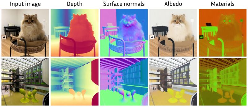
Marigold repurposes Stable Diffusion for dense prediction tasks such as monocular depth estimation and surface normal prediction, delivering a level of detail often missing even in top discriminative models.
Key aspects that make it great: – Reuses the original VAE and only lightly fine-tunes the denoising UNet – Trained on just tens of thousands of synthetic image–modality pairs – Runs on a single consumer GPU (e.g., RTX 4090) – Zero-shot generalization to real-world, in-the-wild images
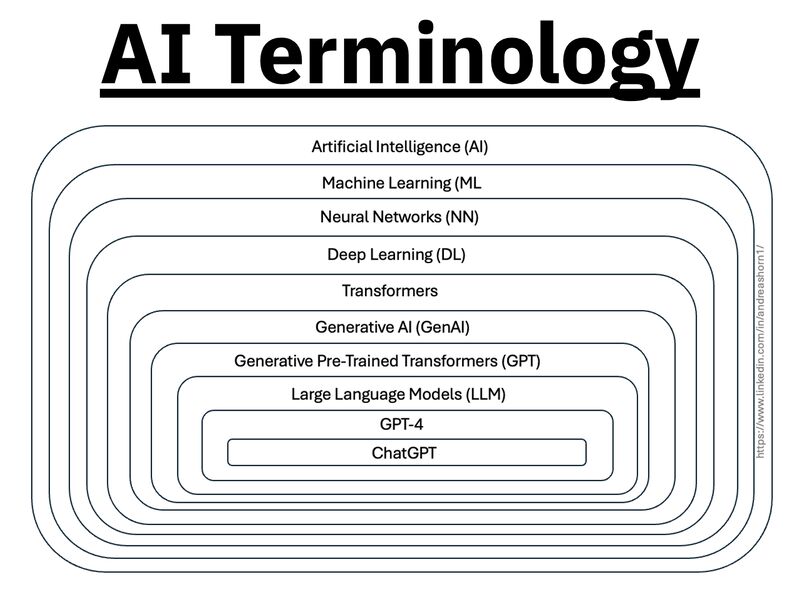
1️⃣ 𝗔𝗿𝘁𝗶𝗳𝗶𝗰𝗶𝗮𝗹 𝗜𝗻𝘁𝗲𝗹𝗹𝗶𝗴𝗲𝗻𝗰𝗲 (𝗔𝗜) – The broadest category, covering automation, reasoning, and decision-making. Early AI was rule-based, but today, it’s mainly data-driven. 2️⃣ 𝗠𝗮𝗰𝗵𝗶𝗻𝗲 𝗟𝗲𝗮𝗿𝗻𝗶𝗻𝗴 (𝗠𝗟) – AI that learns patterns from data without explicit programming. Includes decision trees, clustering, and regression models. 3️⃣ 𝗡𝗲𝘂𝗿𝗮𝗹 𝗡𝗲𝘁𝘄𝗼𝗿𝗸𝘀 (𝗡𝗡) – A subset of ML, inspired by the human brain, designed for pattern recognition and feature extraction. 4️⃣ 𝗗𝗲𝗲𝗽 𝗟𝗲𝗮𝗿𝗻𝗶𝗻𝗴 (𝗗𝗟) – Multi-layered neural networks that drives a lot of modern AI advancements, for example enabling image recognition, speech processing, and more. 5️⃣ 𝗧𝗿𝗮𝗻𝘀𝗳𝗼𝗿𝗺𝗲𝗿𝘀 – A revolutionary deep learning architecture introduced by Google in 2017 that allows models to understand and generate language efficiently. 6️⃣ 𝗚𝗲𝗻𝗲𝗿𝗮𝘁𝗶𝘃𝗲 𝗔𝗜 (𝗚𝗲𝗻𝗔𝗜) – AI that doesn’t just analyze data—it creates. From text and images to music and code, this layer powers today’s most advanced AI models. 7️⃣ 𝗚𝗲𝗻𝗲𝗿𝗮𝘁𝗶𝘃𝗲 𝗣𝗿𝗲-𝗧𝗿𝗮𝗶𝗻𝗲𝗱 𝗧𝗿𝗮𝗻𝘀𝗳𝗼𝗿𝗺𝗲𝗿𝘀 (𝗚𝗣𝗧) – A specific subset of Generative AI that uses transformers for text generation. 8️⃣ 𝗟𝗮𝗿𝗴𝗲 𝗟𝗮𝗻𝗴𝘂𝗮𝗴𝗲 𝗠𝗼𝗱𝗲𝗹𝘀 (𝗟𝗟𝗠) – Massive AI models trained on extensive datasets to understand and generate human-like language. 9️⃣ 𝗚𝗣𝗧-4 – One of the most advanced LLMs, built on transformer architecture, trained on vast datasets to generate human-like responses. 🔟 𝗖𝗵𝗮𝘁𝗚𝗣𝗧 – A specific application of GPT-4, optimized for conversational AI and interactive use.
RASTERIZATION Rasterisation (or rasterization) is the task of taking the information described in a vector graphics format OR the vertices of triangles making 3D shapes and converting them into a raster image (a series of pixels, dots or lines, which, when displayed together, create the image which was represented via shapes), or in other words “rasterizing” vectors or 3D models onto a 2D plane for display on a computer screen.
For each triangle of a 3D shape, you project the corners of the triangle on the virtual screen with some math (projective geometry). Then you have the position of the 3 corners of the triangle on the pixel screen. Those 3 points have texture coordinates, so you know where in the texture are the 3 corners. The cost is proportional to the number of triangles, and is only a little bit affected by the screen resolution.
In computer graphics, a raster graphics orbitmap image is a dot matrix data structure that represents a generally rectangular grid of pixels (points of color), viewable via a monitor, paper, or other display medium.
With rasterization, objects on the screen are created from a mesh of virtual triangles, or polygons, that create 3D models of objects. A lot of information is associated with each vertex, including its position in space, as well as information about color, texture and its “normal,” which is used to determine the way the surface of an object is facing.
Computers then convert the triangles of the 3D models into pixels, or dots, on a 2D screen. Each pixel can be assigned an initial color value from the data stored in the triangle vertices.
Further pixel processing or “shading,” including changing pixel color based on how lights in the scene hit the pixel, and applying one or more textures to the pixel, combine to generate the final color applied to a pixel.
The main advantage of rasterization is its speed. However, rasterization is simply the process of computing the mapping from scene geometry to pixels and does not prescribe a particular way to compute the color of those pixels. So it cannot take shading, especially the physical light, into account and it cannot promise to get a photorealistic output. That’s a big limitation of rasterization.
There are also multiple problems:
If you have two triangles one is behind the other, you will draw twice all the pixels. you only keep the pixel from the triangle that is closer to you (Z-buffer), but you still do the work twice.
The borders of your triangles are jagged as it is hard to know if a pixel is in the triangle or out. You can do some smoothing on those, that is anti-aliasing.
You have to handle every triangles (including the ones behind you) and then see that they do not touch the screen at all. (we have techniques to mitigate this where we only look at triangles that are in the field of view)
Transparency is hard to handle (you can’t just do an average of the color of overlapping transparent triangles, you have to do it in the right order)
RAY CASTING It is almost the exact reverse of rasterization: you start from the virtual screen instead of the vector or 3D shapes, and you project a ray, starting from each pixel of the screen, until it intersect with a triangle.
The cost is directly correlated to the number of pixels in the screen and you need a really cheap way of finding the first triangle that intersect a ray. In the end, it is more expensive than rasterization but it will, by design, ignore the triangles that are out of the field of view.
You can use it to continue after the first triangle it hit, to take a little bit of the color of the next one, etc… This is useful to handle the border of the triangle cleanly (less jagged) and to handle transparency correctly.
RAYTRACING
Same idea as ray casting except once you hit a triangle you reflect on it and go into a different direction. The number of reflection you allow is the “depth” of your ray tracing. The color of the pixel can be calculated, based off the light source and all the polygons it had to reflect off of to get to that screen pixel.
The easiest way to think of ray tracing is to look around you, right now. The objects you’re seeing are illuminated by beams of light. Now turn that around and follow the path of those beams backwards from your eye to the objects that light interacts with. That’s ray tracing.
Ray tracing is eye-oriented process that needs walking through each pixel looking for what object should be shown there, which is also can be described as a technique that follows a beam of light (in pixels) from a set point and simulates how it reacts when it encounters objects.
Compared with rasterization, ray tracing is hard to be implemented in real time, since even one ray can be traced and processed without much trouble, but after one ray bounces off an object, it can turn into 10 rays, and those 10 can turn into 100, 1000…The increase is exponential, and the the calculation for all these rays will be time consuming.
Historically, computer hardware hasn’t been fast enough to use these techniques in real time, such as in video games. Moviemakers can take as long as they like to render a single frame, so they do it offline in render farms. Video games have only a fraction of a second. As a result, most real-time graphics rely on the another technique called rasterization.
PATH TRACING Path tracing can be used to solve more complex lighting situations. Path tracing is a type of ray tracing. When using path tracing for rendering, the rays only produce a single ray per bounce. The rays do not follow a defined line per bounce(to a light, for example), but rather shoot off in a random direction. The path tracing algorithm then takes a random sampling of all of the rays to create the final image. This results in sampling a variety of different types of lighting.
When a ray hits a surface it doesn’t trace a path to every light source, instead it bounces the ray off the surface and keeps bouncing it until it hits a light source or exhausts some bounce limit. It then calculates the amount of light transferred all the way to the pixel, including any color information gathered from surfaces along the way. It then averages out the values calculated from all the paths that were traced into the scene to get the final pixel color value.
It requires a ton of computing power and if you don’t send out enough rays per pixel or don’t trace the paths far enough into the scene then you end up with a very spotty image as many pixels fail to find any light sources from their rays. So when you increase the the samples per pixel, you can see the image quality becomes better and better.
Ray tracing tends to be more efficient than path tracing. Basically, the render time of a ray tracer depends on the number of polygons in the scene. The more polygons you have, the longer it will take. Meanwhile, the rendering time of a path tracer can be indifferent to the number of polygons, but it is related to light situation: If you add a light, transparency, translucence, or other shader effects, the path tracer will slow down considerably.
Spectral sensitivity of eye is influenced by light intensity. And the light intensity determines the level of activity of cones cell and rod cell. This is the main characteristic of human vision. Sensitivity to individual colors, in other words, wavelengths of the light spectrum, is explained by the RGB (red-green-blue) theory. This theory assumed that there are three kinds of cones. It’s selectively sensitive to red (700-630 nm), green (560-500 nm), and blue (490-450 nm) light. And their mutual interaction allow to perceive all colors of the spectrum.


