ACES 2.0 is the second major release of the components that make up the ACES system. The most significant change is a new suite of rendering transforms whose design was informed by collected feedback and requests from users of ACES 1. The changes aim to improve the appearance of perceived artifacts and to complete previously unfinished components of the system, resulting in a more complete, robust, and consistent product.
Highlights of the key changes in ACES 2.0 are as follows:
New output transforms, including:
A less aggressive tone scale
More intuitive controls to create custom outputs to non-standard displays
Robust gamut mapping to improve perceptual uniformity
Improved performance of the inverse transforms
Enhanced AMF specification
An updated specification for ACES Transform IDs
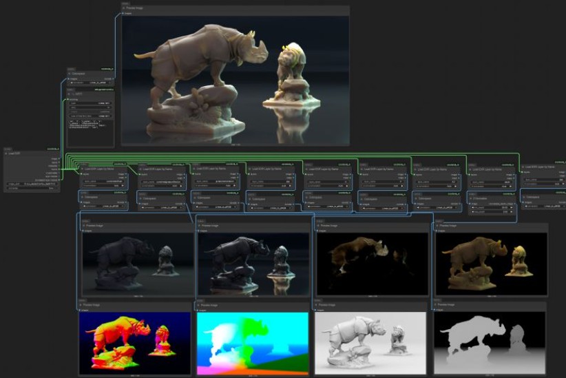
OpenEXR compression recommendations
Enhanced tools for generating Input Transforms and recommended procedures for characterizing prosumer cameras
Look Transform Library
Expanded documentation
Rendering Transform
The most substantial change in ACES 2.0 is a complete redesign of the rendering transform.
ACES 2.0 was built as a unified system, rather than through piecemeal additions. Different deliverable outputs “match” better and making outputs to display setups other than the provided presets is intended to be user-driven. The rendering transforms are less likely to produce undesirable artifacts “out of the box”, which means less time can be spent fixing problematic images and more time making pictures look the way you want.
Key design goals
Improve consistency of tone scale and provide an easy to use parameter to allow for outputs between preset dynamic ranges
Minimize hue skews across exposure range in a region of same hue
Unify for structural consistency across transform type
Easy to use parameters to create outputs other than the presets
Robust gamut mapping to improve harsh clipping artifacts
Fill extents of output code value cube (where appropriate and expected)
Invertible – not necessarily reversible, but Output > ACES > Output round-trip should be possible
Accomplish all of the above while maintaining an acceptable “out-of-the box” rendering
There are several free or open-source VFX asset management systems available that can be used in production environments. These tools vary in scope—from lightweight tools to full-fledged pipeline frameworks. Below is a breakdown of the most notable ones and what makes them stand out.
1. Free & Open-Source VFX Asset Management Systems
1.1 OpenPype (formerly Pype)
License: Open source (Apache 2.0)
– Asset management and project structure setup – Integrates with Maya, Houdini, Nuke, Blender, and others – Includes publishing, versioning, and task tracking – Web interface (OpenPype Studio) for overview and management
Strengths: Actively developed, modular and extendable, production-proven in real studios
– Production tracking, shot management – Web-based interface with intuitive UX – Built-in review and feedback system – API for integration into pipelines
Strengths: Great for team collaboration, focuses on communication between departments
License: Proprietary (older versions may be available for small studios/educational users)
– Project management, review, and pipeline integration – Strength: Industry-proven Note: Current versions are commercial; older community editions may still be used.
1.4 Tactic
License: Open source (EPL 1.0)
– General-purpose asset and workflow management – Web-based, highly configurable
Strengths: Adaptable to VFX pipelines, powerful templating/scripting
Drawbacks: Steep learning curve, not VFX-specific out of the box
Why: – Specifically built for VFX and animation pipelines – Extensively integrates with key DCCs – Actively maintained with a large community – Includes both asset and task management – Works out-of-the-box but is customizable
Stitch is available for free of charge with certain usage limits. Each user receives a monthly allowance of 350 generations using Flash mode and 50 generations using Experimental mode. Please note that these limits are subject to change.
There are three models, two are available now, and a third open-weight version is coming soon:
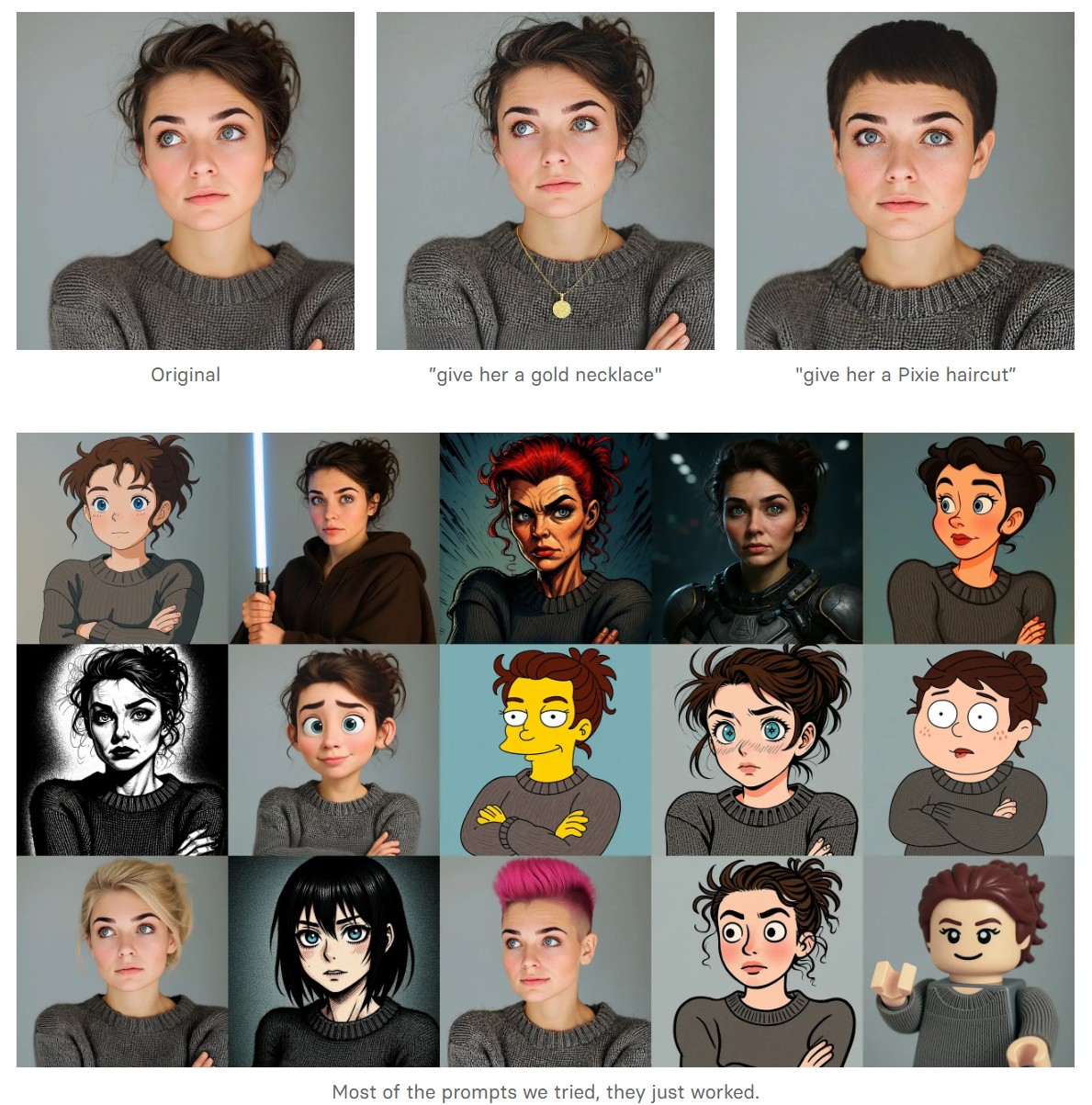
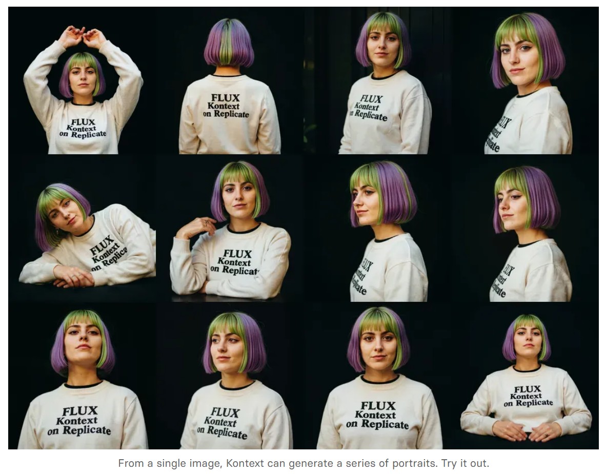
FLUX.1 Kontext [pro]: State-of-the-art performance for image editing. High-quality outputs, great prompt following, and consistent results.
FLUX.1 Kontext [max]: A premium model that brings maximum performance, improved prompt adherence, and high-quality typography generation without compromise on speed.
Coming soon: FLUX.1 Kontext [dev]: An open-weight, guidance-distilled version of Kontext.
We’re so excited with what Kontext can do, we’ve created a collection of models on Replicate to give you ideas:
DB Browser for SQLite (DB4S) is a high quality, visual, open source tool designed for people who want to create, search, and edit SQLite or SQLCipher database files. DB4S gives a familiar spreadsheet-like interface on the database in addition to providing a full SQL query facility. It works with Windows, macOS, and most versions of Linux and Unix. Documentation for the program is on the wiki.
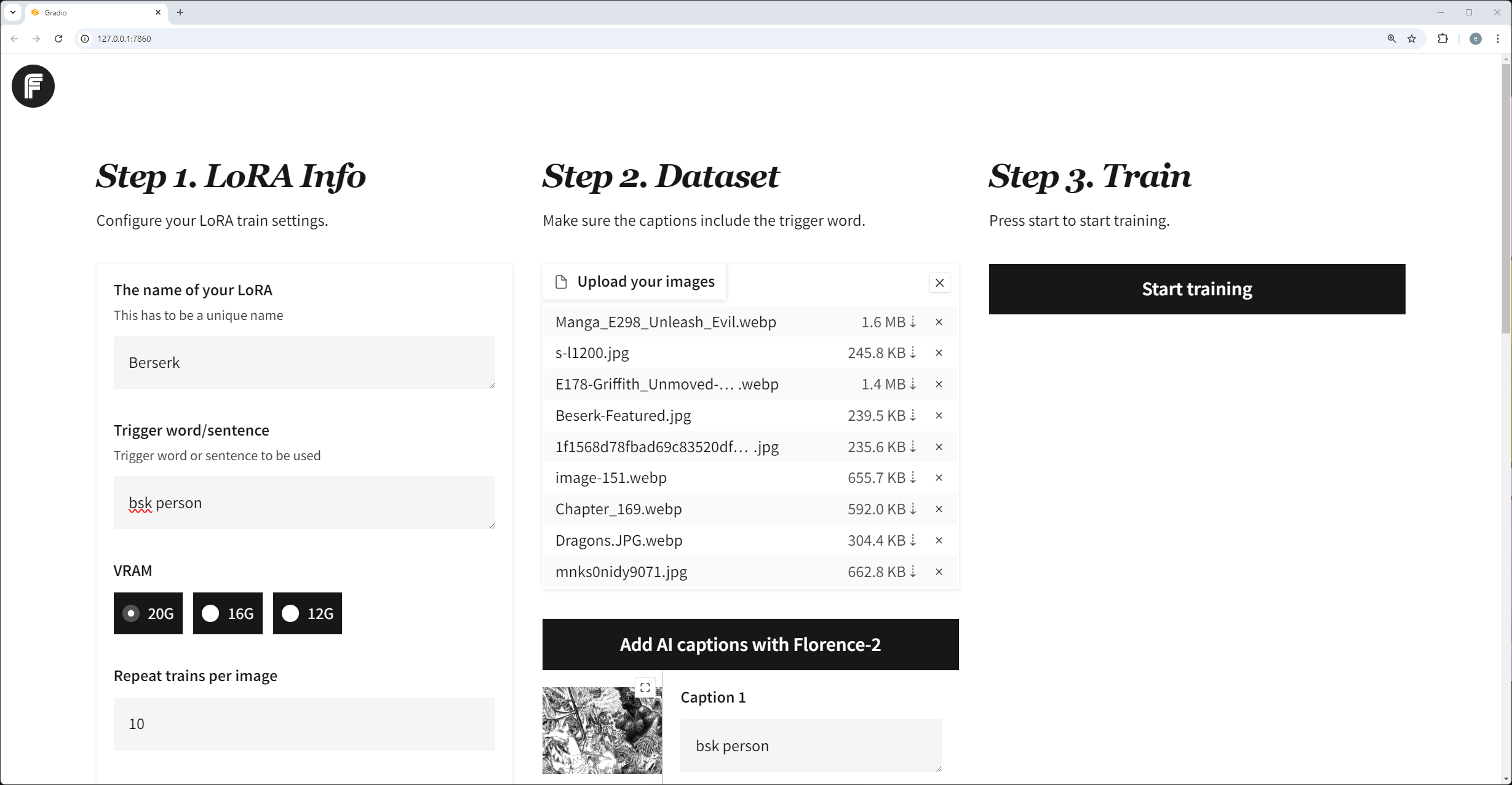
If you’re serious about AI Agents, this is the guide you’ve been waiting for. It’s packed with everything you need to build powerful AI agents. It follows a very hands-on approach that cuts down your time and avoids the common mistakes most developers make.
Andreas Horn on AI Agents vs Agentic AI
1. 𝗔𝗜 𝗔𝗴𝗲𝗻𝘁𝘀: 𝗧𝗼𝗼𝗹𝘀 𝘄𝗶𝘁𝗵 𝗔𝘂𝘁𝗼𝗻𝗼𝗺𝘆, 𝗪𝗶𝘁𝗵𝗶𝗻 𝗟𝗶𝗺𝗶𝘁𝘀 ➜ AI agents are modular, goal-directed systems that operate within clearly defined boundaries. They’re built to: * Use tools (APIs, browsers, databases) * Execute specific, task-oriented workflows * React to prompts or real-time inputs * Plan short sequences and return actionable outputs
But even the most advanced are limited by scope. They don’t initiate. They don’t collaborate. They execute what we ask!
2. 𝗔𝗴𝗲𝗻𝘁𝗶𝗰 𝗔𝗜: 𝗔 𝗦𝘆𝘀𝘁𝗲𝗺 𝗼𝗳 𝗦𝘆𝘀𝘁𝗲𝗺𝘀 ➜ Agentic AI is an architectural leap. It’s not just one smarter agent — it’s multiple specialized agents working together toward shared goals. These systems exhibit: * Multi-agent collaboration * Goal decomposition and role assignment * Inter-agent communication via memory or messaging * Persistent context across time and tasks * Recursive planning and error recovery * Distributed orchestration and adaptive feedback
Agentic AI systems don’t just follow instructions. They coordinate. They adapt. They manage complexity.
The new Vancouver virtual stage will measure 50 feet in diameter, 23 feet tall, and will have a 14 foot deep semi-circle to surround actors and physical sets with a digital environment. There’s also two movable wild walls 20 feet wide and 16.5 feet tall and mounted on a ground-hover system to allow quick repositioning, especially for capturing car driving scenes.
The Windows “Robust File Copy” utility for efficiently copying files and directories, with built-in retry, logging, and mirroring capabilities.
By default, Robocopy skips copying existing files if the specific metadata of the files match.
/mir : Mirror the source directory tree to the destination (equivalent to /e + /purge): /e : copies all subdirectories, including empty ones /purge : deletes files/folders at the destination that no longer exist at the source /sj : Copy NTFS junction points (“soft-links”) themselves rather than what they point to. This preserves the junction at the destination. /sl : Copy symbolic links as links (don’t follow them and copy the target file/directory). /mt:24 :Run the copy operation using 24 concurrent threads (range 1–128; default is 8), for higher throughput on multi-core systems. This switch cannot be combined with /ipg or /efsraw. /J : unbuffered I/O (good for large files) /R:<N> : to limit retries (default is 1 000 000) /W:<S> : to set the wait time in seconds (default is 30) /NJS : No Job Summary. /NC : No Class – don’t log file classes. /NFL : (No File List) Suppresses the per-file lines (e.g. “New File …”, “Copied …”). Benefit: Cuts down console I/O, often shaving 10–20 % off total runtime on large trees. /NDL : (No Directory List) Suppresses the per-directory header lines. Benefit: Further reduces console chatter. /NP : (No Progress) Suppresses the percentage-complete on each file. Drawback: You lose the “XX %” indicator /NJH : (No Job Header) and /NJS (No Job Summary) Only affect the very first and very last block; negligible on runtime and you probably want at least the summary. /NS (No Size) and /NC (No Class) Remove size and class columns from each line. If you’re suppressing file/directory lists anyway, these don’t help much. /XD : ignore given types /ETA : Show Estimated Time of Arrival of copied files.
Note: Robocopy’s support for NTFS reparse-points (symbolic links and junctions) is a bit quirky:
/SL only affects symbolic links (it tells RoboCopy to replicate the link itself rather than follow it).
/SJ only affects junction points (ditto for directory-junction reparse points).
If you use both /SL and /SJ, RoboCopy can still attempt to enumerate a link as a real folder—leading to that “ERROR 267: The directory name is invalid.”
Because of this, this errors can be ignored: 2025/05/15 12:09:11 ERROR 267 (0x0000010B) Copying Directory C:\redux-remember\The directory name is invalid.
Bat file example:
@echo off
setlocal

:: Define the source and destination directories
set "src=%cd%"
set "dst=C:\TEMP"

echo Copying %src% to %dst%
:: Use robocopy to copy the contents
robocopy "%src%" "%dst%" /MIR /SJ /SL /MT:24 /J /R:0 /W:2 /NFL /NDL /ETA /NP /NC /XD "__pycache__" ".pnpm"

pause
endlocal
W_hotbox is basically a fully customisable ‘favourites menu’ that pops up for as long as you press the shortcut and disappears as soon as you release. The buttons that make up the menu represent python scripts and change depending on you selection. The ‘Hotbox Manager’ offers you an user friendly interface which allows you to add new buttons on the fly. Those buttons are directly accessible via buttons that appear in the menu under your cursor.
DISCLAIMER – Links and images on this website may be protected by the respective owners’ copyright. All data submitted by users through this site shall be treated as freely available to share.