


BREAKING NEWS
LATEST POSTS
-
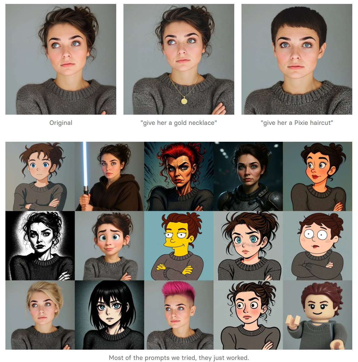
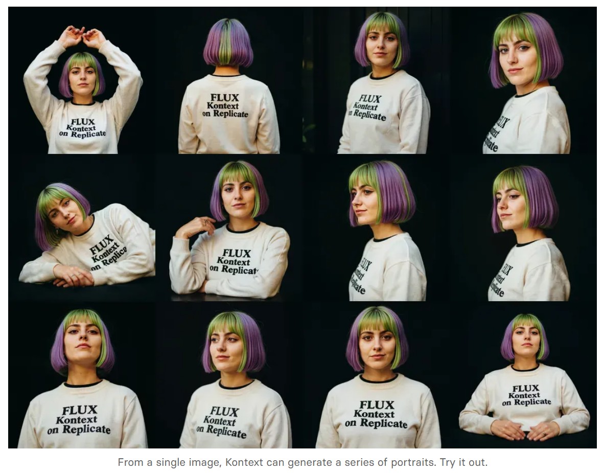
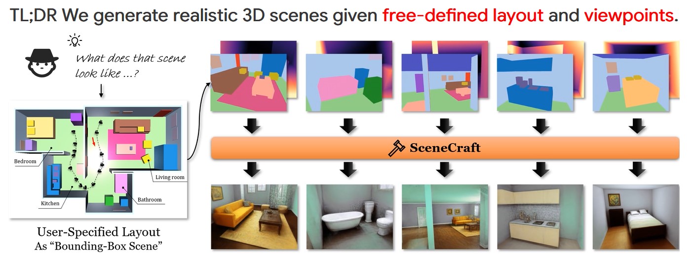
Black Forest Labs released FLUX.1 Kontext
https://replicate.com/blog/flux-kontext
https://replicate.com/black-forest-labs/flux-kontext-pro
There are three models, two are available now, and a third open-weight version is coming soon:
- FLUX.1 Kontext [pro]: State-of-the-art performance for image editing. High-quality outputs, great prompt following, and consistent results.
- FLUX.1 Kontext [max]: A premium model that brings maximum performance, improved prompt adherence, and high-quality typography generation without compromise on speed.
- Coming soon: FLUX.1 Kontext [dev]: An open-weight, guidance-distilled version of Kontext.
We’re so excited with what Kontext can do, we’ve created a collection of models on Replicate to give you ideas:
- Multi-image kontext: Combine two images into one.
- Portrait series: Generate a series of portraits from a single image
- Change haircut: Change a person’s hair style and color
- Iconic locations: Put yourself in front of famous landmarks
- Professional headshot: Generate a professional headshot from any image
-
AI Models – A walkthrough by Andreas Horn
the 8 most important model types and what they’re actually built to do: ⬇️
1. 𝗟𝗟𝗠 – 𝗟𝗮𝗿𝗴𝗲 𝗟𝗮𝗻𝗴𝘂𝗮𝗴𝗲 𝗠𝗼𝗱𝗲𝗹
→ Your ChatGPT-style model.
Handles text, predicts the next token, and powers 90% of GenAI hype.
🛠 Use case: content, code, convos.
2. 𝗟𝗖𝗠 – 𝗟𝗮𝘁𝗲𝗻𝘁 𝗖𝗼𝗻𝘀𝗶𝘀𝘁𝗲𝗻𝗰𝘆 𝗠𝗼𝗱𝗲𝗹
→ Lightweight, diffusion-style models.
Fast, quantized, and efficient — perfect for real-time or edge deployment.
🛠 Use case: image generation, optimized inference.
3. 𝗟𝗔𝗠 – 𝗟𝗮𝗻𝗴𝘂𝗮𝗴𝗲 𝗔𝗰𝘁𝗶𝗼𝗻 𝗠𝗼𝗱𝗲𝗹
→ Where LLM meets planning.
Adds memory, task breakdown, and intent recognition.
🛠 Use case: AI agents, tool use, step-by-step execution.
4. 𝗠𝗼𝗘 – 𝗠𝗶𝘅𝘁𝘂𝗿𝗲 𝗼𝗳 𝗘𝘅𝗽𝗲𝗿𝘁𝘀
→ One model, many minds.
Routes input to the right “expert” model slice — dynamic, scalable, efficient.
🛠 Use case: high-performance model serving at low compute cost.
5. 𝗩𝗟𝗠 – 𝗩𝗶𝘀𝗶𝗼𝗻 𝗟𝗮𝗻𝗴𝘂𝗮𝗴𝗲 𝗠𝗼𝗱𝗲𝗹
→ Multimodal beast.
Combines image + text understanding via shared embeddings.
🛠 Use case: Gemini, GPT-4o, search, robotics, assistive tech.
6. 𝗦𝗟𝗠 – 𝗦𝗺𝗮𝗹𝗹 𝗟𝗮𝗻𝗴𝘂𝗮𝗴𝗲 𝗠𝗼𝗱𝗲𝗹
→ Tiny but mighty.
Designed for edge use, fast inference, low latency, efficient memory.
🛠 Use case: on-device AI, chatbots, privacy-first GenAI.
7. 𝗠𝗟𝗠 – 𝗠𝗮𝘀𝗸𝗲𝗱 𝗟𝗮𝗻𝗴𝘂𝗮𝗴𝗲 𝗠𝗼𝗱𝗲𝗹
→ The OG foundation model.
Predicts masked tokens using bidirectional context.
🛠 Use case: search, classification, embeddings, pretraining.
8. 𝗦𝗔𝗠 – 𝗦𝗲𝗴𝗺𝗲𝗻𝘁 𝗔𝗻𝘆𝘁𝗵𝗶𝗻𝗴 𝗠𝗼𝗱𝗲𝗹
→ Vision model for pixel-level understanding.
Highlights, segments, and understands *everything* in an image.
🛠 Use case: medical imaging, AR, robotics, visual agents.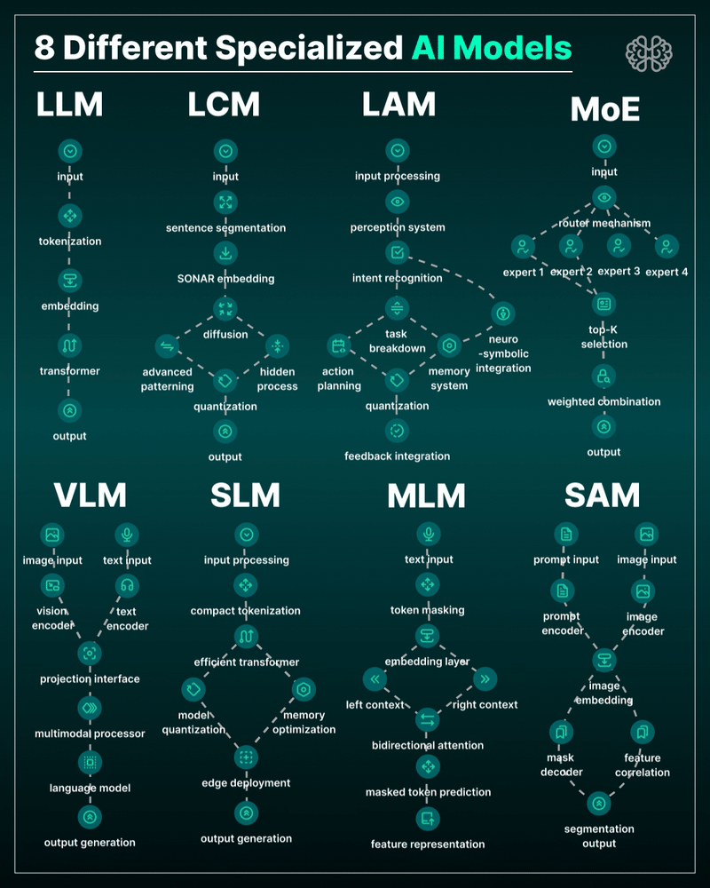
-
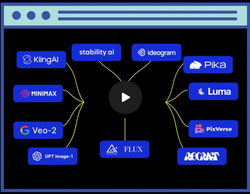
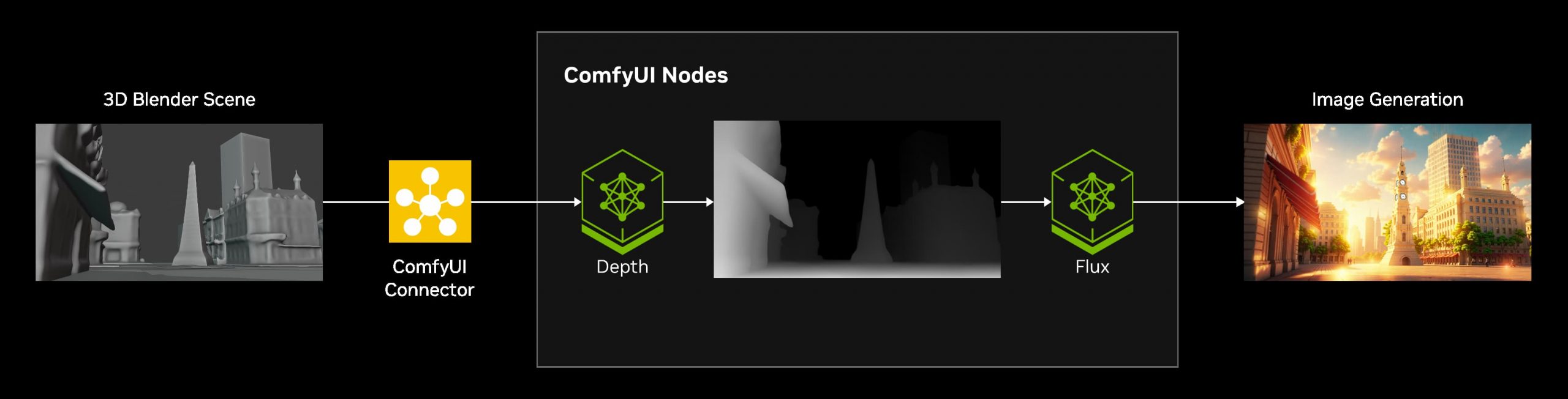
Introducting ComfyUI Native API Nodes
https://blog.comfy.org/p/comfyui-native-api-nodes
Models Supported
- Black Forest Labs Flux 1.1[pro] Ultra, Flux .1[pro]
- Kling 2.0, 1.6, 1.5 & Various Effects
- Luma Photon, Ray2, Ray1.6
- MiniMax Text-to-Video, Image-to-Video
- PixVerse V4 & Effects
- Recraft V3, V2 & Various Tools
- Stability AI Stable Image Ultra, Stable Diffusion 3.5 Large
- Google Veo2
- Ideogram V3, V2, V1
- OpenAI GPT4o image
- Pika 2.2
-
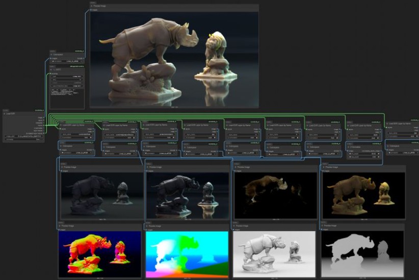
ComfyUI-CoCoTools_IO – A set of nodes focused on advanced image I/O operations, particularly for EXR file handling
https://github.com/Conor-Collins/ComfyUI-CoCoTools_IO
Features
- Advanced EXR image input with multilayer support
- EXR layer extraction and manipulation
- High-quality image saving with format-specific options
- Standard image format loading with bit depth awareness
Current Nodes
Image I/O
- Image Loader: Load standard image formats (PNG, JPG, WebP, etc.) with proper bit depth handling
- Load EXR: Comprehensive EXR file loading with support for multiple layers, channels, and cryptomatte data
- Load EXR Layer by Name: Extract specific layers from EXR files (similar to Nuke’s Shuffle node)
- Cryptomatte Layer: Specialized handling for cryptomatte layers in EXR files
- Image Saver: Save images in various formats with format-specific options (bit depth, compression, etc.)
Image Processing
- Colorspace: Convert between sRGB and Linear colorspaces
- Z Normalize: Normalize depth maps and other single-channel data
-
Claudio Tosti – La vita pittoresca dell’abate Uggeri
https://vivariumnovum.it/saggistica/varia/la-vita-pittoresca-dellabate-uggeri
Book author: Claudio Tosti
Title: La vita pittoresca dell’abate Uggeri – Vol. I – La Giornata Tuscolana- ISBN: 978-8895611990
Video made with Pixverse.ai and DaVinci Resolve
-
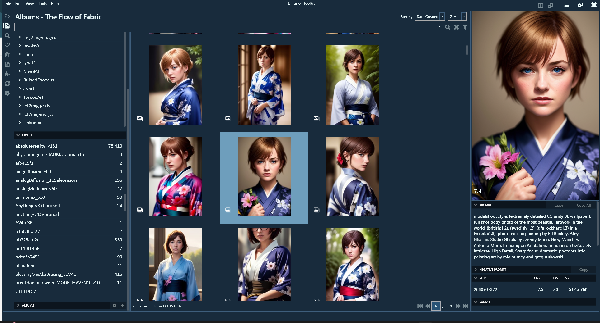
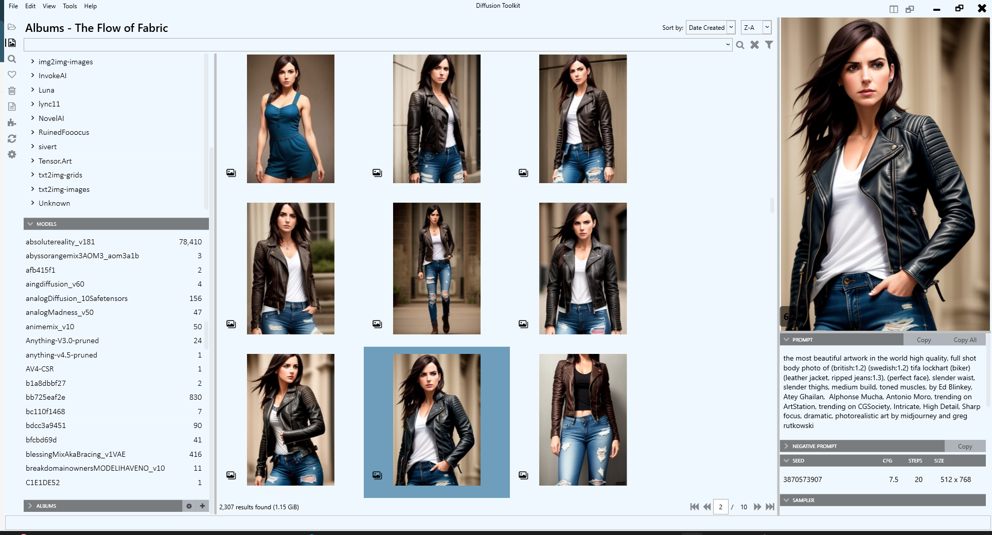
DiffusionToolkit – An image metadata-indexer and viewer for AI-generated images
https://github.com/RupertAvery/DiffusionToolkit
It aims to help you organize, search and sort your ever-growing collection.
https://github.com/RupertAvery/DiffusionToolkit/blob/master/Diffusion.Toolkit/Tips.md
-
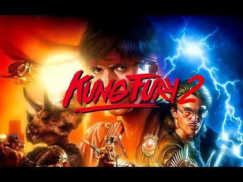
KUNG FURY 2 movie trailer
David Sandberg has responded and said “This was an internal promo video that was never supposed to be seen by the public. I feel bad because it contains a bunch of plot points and temp VFX,” Sandberg told Variety in a statement. “I hope at least people can see the passion that we poured into the movie, the world deserves to see it as it was meant to be seen. This movie has been held hostage for the past 5 years but I promise to keep fighting for it and make sure this film gets the chance it truly deserves.”


FEATURED POSTS


-
What’s the Difference Between Ray Casting, Ray Tracing, Path Tracing and Rasterization? Physical light tracing…
RASTERIZATION
Rasterisation (or rasterization) is the task of taking the information described in a vector graphics format OR the vertices of triangles making 3D shapes and converting them into a raster image (a series of pixels, dots or lines, which, when displayed together, create the image which was represented via shapes), or in other words “rasterizing” vectors or 3D models onto a 2D plane for display on a computer screen.For each triangle of a 3D shape, you project the corners of the triangle on the virtual screen with some math (projective geometry). Then you have the position of the 3 corners of the triangle on the pixel screen. Those 3 points have texture coordinates, so you know where in the texture are the 3 corners. The cost is proportional to the number of triangles, and is only a little bit affected by the screen resolution.
In computer graphics, a raster graphics or bitmap image is a dot matrix data structure that represents a generally rectangular grid of pixels (points of color), viewable via a monitor, paper, or other display medium.
With rasterization, objects on the screen are created from a mesh of virtual triangles, or polygons, that create 3D models of objects. A lot of information is associated with each vertex, including its position in space, as well as information about color, texture and its “normal,” which is used to determine the way the surface of an object is facing.
Computers then convert the triangles of the 3D models into pixels, or dots, on a 2D screen. Each pixel can be assigned an initial color value from the data stored in the triangle vertices.
Further pixel processing or “shading,” including changing pixel color based on how lights in the scene hit the pixel, and applying one or more textures to the pixel, combine to generate the final color applied to a pixel.
The main advantage of rasterization is its speed. However, rasterization is simply the process of computing the mapping from scene geometry to pixels and does not prescribe a particular way to compute the color of those pixels. So it cannot take shading, especially the physical light, into account and it cannot promise to get a photorealistic output. That’s a big limitation of rasterization.
There are also multiple problems:
If you have two triangles one is behind the other, you will draw twice all the pixels. you only keep the pixel from the triangle that is closer to you (Z-buffer), but you still do the work twice.
The borders of your triangles are jagged as it is hard to know if a pixel is in the triangle or out. You can do some smoothing on those, that is anti-aliasing.
You have to handle every triangles (including the ones behind you) and then see that they do not touch the screen at all. (we have techniques to mitigate this where we only look at triangles that are in the field of view)
Transparency is hard to handle (you can’t just do an average of the color of overlapping transparent triangles, you have to do it in the right order)


RAY CASTING
It is almost the exact reverse of rasterization: you start from the virtual screen instead of the vector or 3D shapes, and you project a ray, starting from each pixel of the screen, until it intersect with a triangle.The cost is directly correlated to the number of pixels in the screen and you need a really cheap way of finding the first triangle that intersect a ray. In the end, it is more expensive than rasterization but it will, by design, ignore the triangles that are out of the field of view.
You can use it to continue after the first triangle it hit, to take a little bit of the color of the next one, etc… This is useful to handle the border of the triangle cleanly (less jagged) and to handle transparency correctly.
RAYTRACING


Same idea as ray casting except once you hit a triangle you reflect on it and go into a different direction. The number of reflection you allow is the “depth” of your ray tracing. The color of the pixel can be calculated, based off the light source and all the polygons it had to reflect off of to get to that screen pixel.The easiest way to think of ray tracing is to look around you, right now. The objects you’re seeing are illuminated by beams of light. Now turn that around and follow the path of those beams backwards from your eye to the objects that light interacts with. That’s ray tracing.
Ray tracing is eye-oriented process that needs walking through each pixel looking for what object should be shown there, which is also can be described as a technique that follows a beam of light (in pixels) from a set point and simulates how it reacts when it encounters objects.
Compared with rasterization, ray tracing is hard to be implemented in real time, since even one ray can be traced and processed without much trouble, but after one ray bounces off an object, it can turn into 10 rays, and those 10 can turn into 100, 1000…The increase is exponential, and the the calculation for all these rays will be time consuming.
Historically, computer hardware hasn’t been fast enough to use these techniques in real time, such as in video games. Moviemakers can take as long as they like to render a single frame, so they do it offline in render farms. Video games have only a fraction of a second. As a result, most real-time graphics rely on the another technique called rasterization.

PATH TRACING
Path tracing can be used to solve more complex lighting situations.
Path tracing is a type of ray tracing. When using path tracing for rendering, the rays only produce a single ray per bounce. The rays do not follow a defined line per bounce (to a light, for example), but rather shoot off in a random direction. The path tracing algorithm then takes a random sampling of all of the rays to create the final image. This results in sampling a variety of different types of lighting.When a ray hits a surface it doesn’t trace a path to every light source, instead it bounces the ray off the surface and keeps bouncing it until it hits a light source or exhausts some bounce limit.
It then calculates the amount of light transferred all the way to the pixel, including any color information gathered from surfaces along the way.
It then averages out the values calculated from all the paths that were traced into the scene to get the final pixel color value.It requires a ton of computing power and if you don’t send out enough rays per pixel or don’t trace the paths far enough into the scene then you end up with a very spotty image as many pixels fail to find any light sources from their rays. So when you increase the the samples per pixel, you can see the image quality becomes better and better.
Ray tracing tends to be more efficient than path tracing. Basically, the render time of a ray tracer depends on the number of polygons in the scene. The more polygons you have, the longer it will take.
Meanwhile, the rendering time of a path tracer can be indifferent to the number of polygons, but it is related to light situation: If you add a light, transparency, translucence, or other shader effects, the path tracer will slow down considerably.
blogs.nvidia.com/blog/2018/03/19/whats-difference-between-ray-tracing-rasterization/
https://en.wikipedia.org/wiki/Rasterisation
https://www.quora.com/Whats-the-difference-between-ray-tracing-and-path-tracing
-
HDRI Median Cut plugin
www.hdrlabs.com/picturenaut/plugins.html

Note. The Median Cut algorithm is typically used for color quantization, which involves reducing the number of colors in an image while preserving its visual quality. It doesn’t directly provide a way to identify the brightest areas in an image. However, if you’re interested in identifying the brightest areas, you might want to look into other methods like thresholding, histogram analysis, or edge detection, through openCV for example.
Here is an openCV example:
(more…)


