Search Results for: real-time
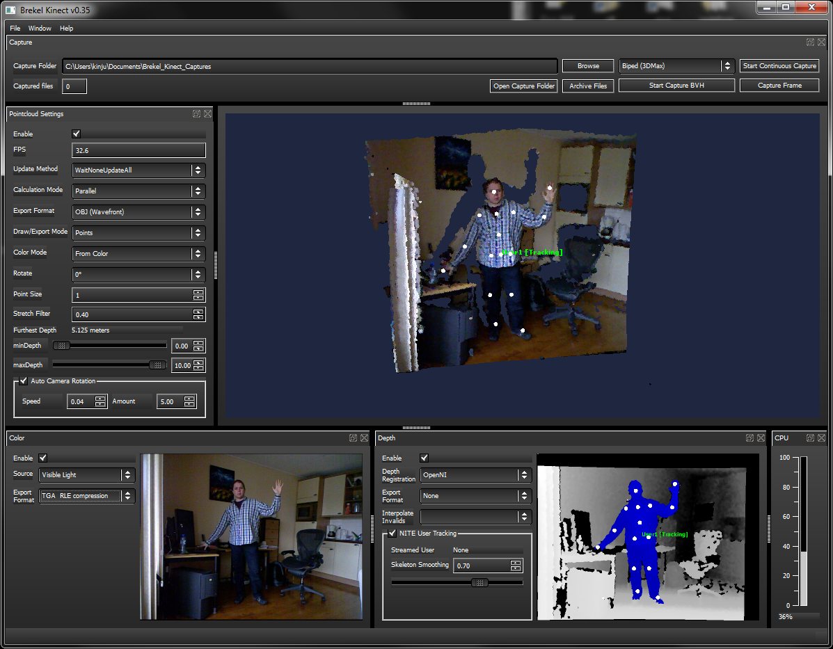
Brekel kinect real-time motion capture
http://www.brekel.com/?page_id=155
It allows you to capture 3D objects and export them to disk for use in 3D packages. As well as do skeleton tracking which can be streamed into Autodesk’s MotionBuilder in realtime, or exported as BVH files.
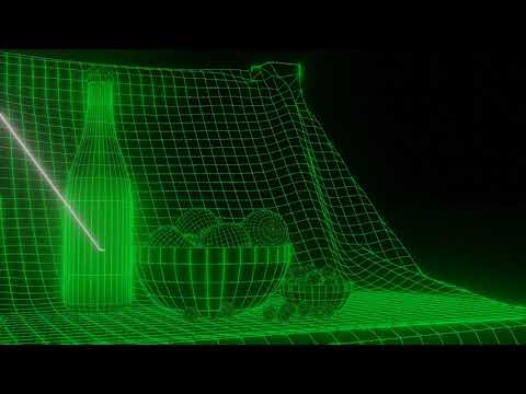
Euclideon Unlimited Detail Real-Time Rendering Technology Preview 2011
Unreal Nanite precursor?
Rafael Perez – RIFE, an interpolation retimer for Nuke
This project implements RIFE – Real-Time Intermediate Flow Estimation for Video Frame Interpolation for The Foundry’s Nuke.
RIFE is a powerful frame interpolation neural network, capable of high-quality retimes and optical flow estimation.
This implementation allows RIFE to be used natively inside Nuke without any external dependencies or complex installations. It wraps the network in an easy-to-use Gizmo with controls similar to those in OFlow or Kronos.
https://github.com/rafaelperez/RIFE-for-Nuke
VR-NeRF: High-Fidelity Virtualized Walkable Spaces
An end-to-end system for the high-fidelity capture, model reconstruction, and real-time rendering of walkable spaces in virtual reality using neural radiance fields.

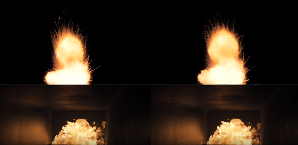
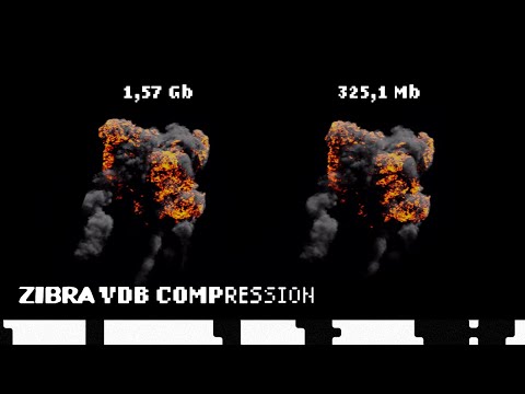
Zibra VDB Compression – a new solution, bringing groundbreaking OpenVDB format to game development
Zibra VDB Compression is the newest ZibraAI solution, being developed to bring film-quality VFX into games with GPU-powered compressed VDB effects.
Born from a custom AI-based technology, it makes it possible to:
- Compress huge VFXs, created in different tools and stored in OpenVDB format, up to 20 times, and add more high-quality volumetric VFX to the game, filling it with lifelike visuals, all without increasing the build size;
- Render volumetric effects in game engines in real-time;
- Reuse a volumetric effect in multiple use cases, optimizing memory consumption;
- Change the way the effect looks in different parts of the project with shaders, regulating color, density, and playback speed, all according to your needs.
Our VDB compression solution also opens new possibilities for realistic scene lighting. With our tech, you can use light data from VFX to light up a scene, add reflections, etc, making your game much more immersive and true to life.
Autodesk open sources Aurora – an interactive path tracing renderer that leverages graphics processing unit (GPU) hardware ray tracing
https://github.com/autodesk/Aurora
Goals for Aurora
- Renders noise-free in 50 milliseconds or less per frame.
- Intended for design iteration (viewport, performance) rather than final frames (production, quality), which are produced from a renderer like Autodesk Arnold.
- OS-independent: Runs on Windows, Linux, MacOS.
- Vendor-independent: Runs on GPUs from AMD, Apple, Intel, NVIDIA.
Features
- Path tracing and the global effects that come with it: soft shadows, reflections, refractions, bounced light, and others.
- Autodesk Standard Surface materials defined with MaterialX documents.
- Arbitrary blended layers of materials, which can be used to implement decals.
- Environment lighting with a wrap-around lat-long image.
- Triangle geometry with object instancing.
- Real-time denoising
- Interactive performance for complex scenes.
- A USD Hydra render delegate called HdAurora.
DDS textures – DirectDraw Surface container file format
The DirectDraw Surface container file format (uses the filename extension DDS), is a Microsoft format for storing data compressed with the previously proprietary S3 Texture Compression (S3TC) algorithm, which can be decompressed in hardware by GPUs. This makes the format useful for storing graphical textures and cubic environment maps as a data file, both compressed and uncompressed.
en.wikipedia.org/wiki/DirectDraw_Surface
The DDS format was developed by Microsoft to be used with the DirectX SDK for the development of real-time rendering applications, particularly 3D games. The format is primarily used to store model textures, mipmap levels, and cubemaps in 3D video games.
Advanced Computer Vision with Python OpenCV and Mediapipe
https://www.freecodecamp.org/news/advanced-computer-vision-with-python/

https://www.freecodecamp.org/news/how-to-use-opencv-and-python-for-computer-vision-and-ai/

Working for a VFX (Visual Effects) studio provides numerous opportunities to leverage the power of Python and OpenCV for various tasks. OpenCV is a versatile computer vision library that can be applied to many aspects of the VFX pipeline. Here’s a detailed list of opportunities to take advantage of Python and OpenCV in a VFX studio:
- Image and Video Processing:
- Preprocessing: Python and OpenCV can be used for tasks like resizing, color correction, noise reduction, and frame interpolation to prepare images and videos for further processing.
- Format Conversion: Convert between different image and video formats using OpenCV’s capabilities.
- Tracking and Matchmoving:
- Feature Detection and Tracking: Utilize OpenCV to detect and track features in image sequences, which is essential for matchmoving tasks to integrate computer-generated elements into live-action footage.
- Rotoscoping and Masking:
- Segmentation and Masking: Use OpenCV for creating and manipulating masks and alpha channels for various VFX tasks, like isolating objects or characters from their backgrounds.
- Camera Calibration:
- Intrinsic and Extrinsic Calibration: Python and OpenCV can help calibrate cameras for accurate 3D scene reconstruction and camera tracking.
- 3D Scene Reconstruction:
- Stereoscopy: Use OpenCV to process stereoscopic image pairs for creating 3D depth maps and generating realistic 3D scenes.
- Structure from Motion (SfM): Implement SfM techniques to create 3D models from 2D image sequences.
- Green Screen and Blue Screen Keying:
- Chroma Keying: Implement advanced keying algorithms using OpenCV to seamlessly integrate actors and objects into virtual environments.
- Particle and Fluid Simulations:
- Particle Tracking: Utilize OpenCV to track and manipulate particles in fluid simulations for more realistic visual effects.
- Motion Analysis:
- Optical Flow: Implement optical flow algorithms to analyze motion patterns in footage, useful for creating dynamic VFX elements that follow the motion of objects.
- Virtual Set Extension:
- Camera Projection: Use camera calibration techniques to project virtual environments onto physical sets, extending the visual scope of a scene.
- Color Grading:
- Color Correction: Implement custom color grading algorithms to match the color tones and moods of different shots.
- Automated QC (Quality Control):
- Artifact Detection: Develop Python scripts to automatically detect and flag visual artifacts like noise, flicker, or compression artifacts in rendered frames.
- Data Analysis and Visualization:
- Performance Metrics: Use Python to analyze rendering times and optimize the rendering process.
- Data Visualization: Generate graphs and charts to visualize render farm usage, project progress, and resource allocation.
- Automating Repetitive Tasks:
- Batch Processing: Automate repetitive tasks like resizing images, applying filters, or converting file formats across multiple shots.
- Machine Learning Integration:
- Object Detection: Integrate machine learning models (using frameworks like TensorFlow or PyTorch) to detect and track specific objects or elements within scenes.
- Pipeline Integration:
- Custom Tools: Develop Python scripts and tools to integrate OpenCV-based processes seamlessly into the studio’s pipeline.
- Real-time Visualization:
- Live Previsualization: Implement real-time OpenCV-based visualizations to aid decision-making during the preproduction stage.
- VR and AR Integration:
- Augmented Reality: Use Python and OpenCV to integrate virtual elements into real-world footage, creating compelling AR experiences.
- Camera Effects:
- Lens Distortion: Correct lens distortions and apply various camera effects using OpenCV, contributing to the desired visual style.
Interpolating frames from an EXR sequence using OpenCV can be useful when you have only every second frame of a final render and you want to create smoother motion by generating intermediate frames. However, keep in mind that interpolating frames might not always yield perfect results, especially if there are complex changes between frames. Here’s a basic example of how you might use OpenCV to achieve this:
import cv2
import numpy as np
import os

# Replace with the path to your EXR frames
exr_folder = "path_to_exr_frames"

# Replace with the appropriate frame extension and naming convention
frame_template = "frame_{:04d}.exr"

# Define the range of frame numbers you have
start_frame = 1
end_frame = 100
step = 2

# Define the output folder for interpolated frames
output_folder = "output_interpolated_frames"
os.makedirs(output_folder, exist_ok=True)

# Loop through the frame range and interpolate
for frame_num in range(start_frame, end_frame + 1, step):
    frame_path = os.path.join(exr_folder, frame_template.format(frame_num))
    next_frame_path = os.path.join(exr_folder, frame_template.format(frame_num + step))

    if os.path.exists(frame_path) and os.path.exists(next_frame_path):
        frame = cv2.imread(frame_path, cv2.IMREAD_ANYDEPTH | cv2.IMREAD_COLOR)
        next_frame = cv2.imread(next_frame_path, cv2.IMREAD_ANYDEPTH | cv2.IMREAD_COLOR)

        # Interpolate frames using simple averaging
        interpolated_frame = (frame + next_frame) / 2

        # Save interpolated frame
        output_path = os.path.join(output_folder, frame_template.format(frame_num))
        cv2.imwrite(output_path, interpolated_frame)

        print(f"Interpolated frame {frame_num}") # alternatively: print("Interpolated frame {}".format(frame_num))
Please note the following points:
- The above example uses simple averaging to interpolate frames. More advanced interpolation methods might provide better results, such as motion-based algorithms like optical flow-based interpolation.
- EXR files can store high dynamic range (HDR) data, so make sure to use cv2.IMREAD_ANYDEPTH flag when reading these files.
- OpenCV might not support EXR format directly. You might need to use a library like exr to read and manipulate EXR files, and then convert them to OpenCV-compatible formats.
- Consider the characteristics of your specific render when using interpolation. If there are large changes between frames, the interpolation might lead to artifacts.
- Experiment with different interpolation methods and parameters to achieve the desired result.
- For a more advanced and accurate interpolation, you might need to implement or use existing algorithms that take into account motion estimation and compensation.
Reuben Wu – Glowing Geometric Light Paintings
www.thisiscolossal.com/2021/04/reuben-wu-ex-stasis/

Wu programmed a stick of 200 LED lights to shift in color and shape above the calm landscapes. He captured the mesmerizing movements in-camera, and through a combination of stills, timelapse, and real-time footage, produced four audiovisual works that juxtapose the natural scenery with the artificially produced light and electronic sounds.
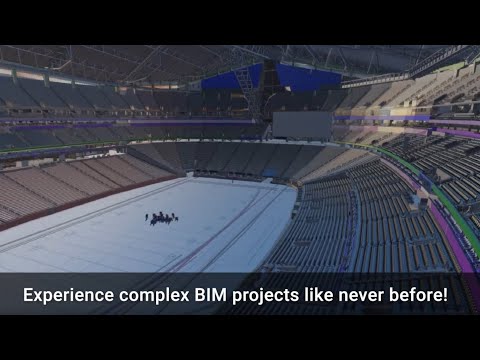
VIM – the fastest way to interact with the biggest BIM projects
VIM is a real-time 3D file format purpose built for AEC’s modern demands.
VIM offers a modern, efficient, and compact 3D data interchange open format to quickly transport design data and geometry from Revit and other BIM sources such as real-time engines and 3D editors.

NVIDIA Real Time Marbles RTX through the Omniverse Platform
Marbles runs on a single Quadro RTX 8000 simulating complex physics in a real-time ray traced world.

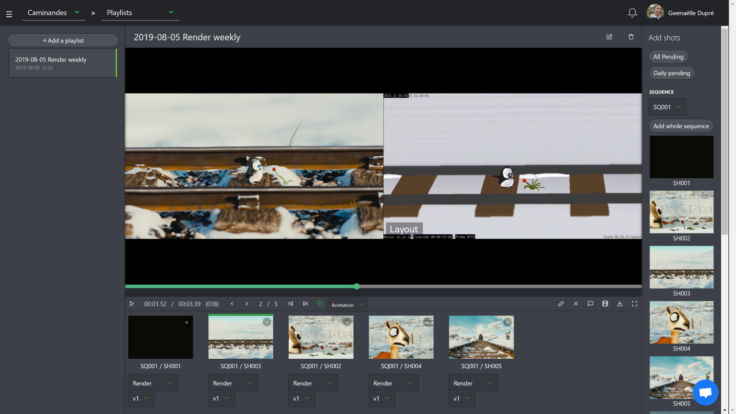
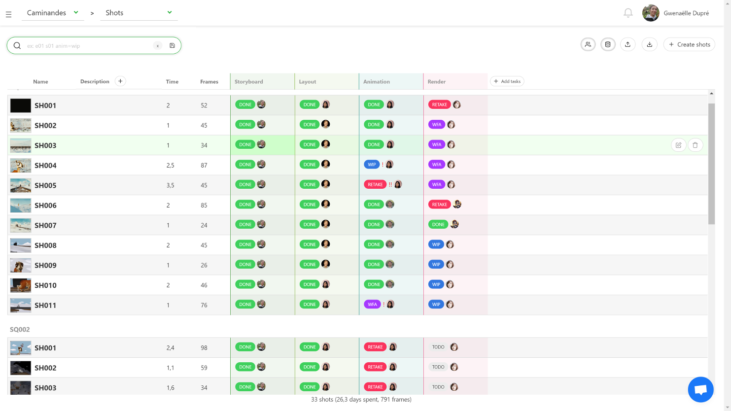
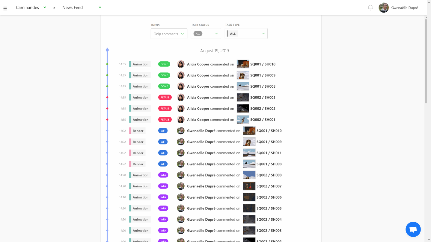
Kitsu Today CGWire – production tracking – pipeline
https://www.cg-wire.com/en/kitsu
Kitsu is a web application to track the progress of your productions. It improves the communication between all stakeholders of the production. Which leads to better pictures and faster deliveries.

CGWire PRESS RELEASE
“We noticed that a good way to improve the quality of CG movies is to improve the communication inside the studio. That’s why we made a software that is easy to use. All the stakeholders of the production can add and get data efficiently. Everyone is better informed and take better decisions.
The most notable features of Kitsu are:
– The listing of all elements of the production: assets, shots and tasks.
– A powerful commenting system that allows to put notes on tasks while changing status and attaching previews.
– A playlist system to view, compare, annotate and comment shots in a row. It’s super easy for the director to perform his reviews.
– A news feed to know in real-time what is happening during the production.
– Quota tables to evaluate the productiviy of the studio.
Aside of that we added other tools to simplify the daily usage : timesheets, scheduling, production statistics, Slack integration and casting management.
Kitsu Today CGWire is deployed in 25 studios. Most of them are split in different locations. So, our users are spread in more than 15 countries working on production of all kinds: TV series, feature films and short movies (our customers are Cube Creative, TNZPV, Miyu, Akami, Lee Film, etc.). Once shipped, all productions tracked with Kitsu met success by receiving awards or getting millions of views on Youtube or on TV.
Another good thing is that Animation Schools really enjoy our product, 10 of them are using Kitsu to manage their end of studies projects (Les Gobelins, Ecole des Nouvelles Images, LISAA, etc.).
Our goal in 2020 is to make the ingestion process even better with a stronger import system, software integration and production templates. With these features, we want to be the reference software for building animation productions, especially for TV series.”
Material X – an open standard for transfer of rich material and look-development content
MaterialX is an open standard for transfer of rich material and look-development content between applications and renderers.
Originated at Lucasfilm in 2012, MaterialX has been used by Industrial Light & Magic in feature films such as Star Wars: The Force Awakens and Rogue One: A Star Wars Story, and by ILMxLAB in real-time experiences such as Trials On Tatooine.
MaterialX addresses the need for a common, open standard to represent the data values and relationships required to transfer the complete look of a computer graphics model from one application or rendering platform to another, including shading networks, patterns and texturing, complex nested materials and geometric assignments.
To further encourage interchangeable CG look setups, MaterialX also defines a complete set of data creation and processing nodes with a precise mechanism for functional extensibility.
Open Source Nvidia Omniverse
blogs.nvidia.com/blog/2019/03/18/omniverse-collaboration-platform/
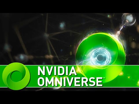
developer.nvidia.com/nvidia-omniverse
An open, Interactive 3D Design Collaboration Platform for Multi-Tool Workflows to simplify studio workflows for real-time graphics.
It supports Pixar’s Universal Scene Description technology for exchanging information about modeling, shading, animation, lighting, visual effects and rendering across multiple applications.
It also supports NVIDIA’s Material Definition Language, which allows artists to exchange information about surface materials across multiple tools.
With Omniverse, artists can see live updates made by other artists working in different applications. They can also see changes reflected in multiple tools at the same time.
For example an artist using Maya with a portal to Omniverse can collaborate with another artist using UE4 and both will see live updates of each others’ changes in their application.
What’s the Difference Between Ray Casting, Ray Tracing, Path Tracing and Rasterization? Physical light tracing…
RASTERIZATION
Rasterisation (or rasterization) is the task of taking the information described in a vector graphics format OR the vertices of triangles making 3D shapes and converting them into a raster image (a series of pixels, dots or lines, which, when displayed together, create the image which was represented via shapes), or in other words “rasterizing” vectors or 3D models onto a 2D plane for display on a computer screen.
For each triangle of a 3D shape, you project the corners of the triangle on the virtual screen with some math (projective geometry). Then you have the position of the 3 corners of the triangle on the pixel screen. Those 3 points have texture coordinates, so you know where in the texture are the 3 corners. The cost is proportional to the number of triangles, and is only a little bit affected by the screen resolution.
In computer graphics, a raster graphics or bitmap image is a dot matrix data structure that represents a generally rectangular grid of pixels (points of color), viewable via a monitor, paper, or other display medium.
With rasterization, objects on the screen are created from a mesh of virtual triangles, or polygons, that create 3D models of objects. A lot of information is associated with each vertex, including its position in space, as well as information about color, texture and its “normal,” which is used to determine the way the surface of an object is facing.
Computers then convert the triangles of the 3D models into pixels, or dots, on a 2D screen. Each pixel can be assigned an initial color value from the data stored in the triangle vertices.
Further pixel processing or “shading,” including changing pixel color based on how lights in the scene hit the pixel, and applying one or more textures to the pixel, combine to generate the final color applied to a pixel.
The main advantage of rasterization is its speed. However, rasterization is simply the process of computing the mapping from scene geometry to pixels and does not prescribe a particular way to compute the color of those pixels. So it cannot take shading, especially the physical light, into account and it cannot promise to get a photorealistic output. That’s a big limitation of rasterization.
There are also multiple problems:
-
If you have two triangles one is behind the other, you will draw twice all the pixels. you only keep the pixel from the triangle that is closer to you (Z-buffer), but you still do the work twice.
-
The borders of your triangles are jagged as it is hard to know if a pixel is in the triangle or out. You can do some smoothing on those, that is anti-aliasing.
-
You have to handle every triangles (including the ones behind you) and then see that they do not touch the screen at all. (we have techniques to mitigate this where we only look at triangles that are in the field of view)
-
Transparency is hard to handle (you can’t just do an average of the color of overlapping transparent triangles, you have to do it in the right order)


RAY CASTING
It is almost the exact reverse of rasterization: you start from the virtual screen instead of the vector or 3D shapes, and you project a ray, starting from each pixel of the screen, until it intersect with a triangle.
The cost is directly correlated to the number of pixels in the screen and you need a really cheap way of finding the first triangle that intersect a ray. In the end, it is more expensive than rasterization but it will, by design, ignore the triangles that are out of the field of view.
You can use it to continue after the first triangle it hit, to take a little bit of the color of the next one, etc… This is useful to handle the border of the triangle cleanly (less jagged) and to handle transparency correctly.
RAYTRACING
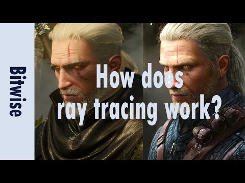
Same idea as ray casting except once you hit a triangle you reflect on it and go into a different direction. The number of reflection you allow is the “depth” of your ray tracing. The color of the pixel can be calculated, based off the light source and all the polygons it had to reflect off of to get to that screen pixel.
The easiest way to think of ray tracing is to look around you, right now. The objects you’re seeing are illuminated by beams of light. Now turn that around and follow the path of those beams backwards from your eye to the objects that light interacts with. That’s ray tracing.
Ray tracing is eye-oriented process that needs walking through each pixel looking for what object should be shown there, which is also can be described as a technique that follows a beam of light (in pixels) from a set point and simulates how it reacts when it encounters objects.
Compared with rasterization, ray tracing is hard to be implemented in real time, since even one ray can be traced and processed without much trouble, but after one ray bounces off an object, it can turn into 10 rays, and those 10 can turn into 100, 1000…The increase is exponential, and the the calculation for all these rays will be time consuming.
Historically, computer hardware hasn’t been fast enough to use these techniques in real time, such as in video games. Moviemakers can take as long as they like to render a single frame, so they do it offline in render farms. Video games have only a fraction of a second. As a result, most real-time graphics rely on the another technique called rasterization.
PATH TRACING
Path tracing can be used to solve more complex lighting situations.
Path tracing is a type of ray tracing. When using path tracing for rendering, the rays only produce a single ray per bounce. The rays do not follow a defined line per bounce (to a light, for example), but rather shoot off in a random direction. The path tracing algorithm then takes a random sampling of all of the rays to create the final image. This results in sampling a variety of different types of lighting.
When a ray hits a surface it doesn’t trace a path to every light source, instead it bounces the ray off the surface and keeps bouncing it until it hits a light source or exhausts some bounce limit.
It then calculates the amount of light transferred all the way to the pixel, including any color information gathered from surfaces along the way.
It then averages out the values calculated from all the paths that were traced into the scene to get the final pixel color value.
It requires a ton of computing power and if you don’t send out enough rays per pixel or don’t trace the paths far enough into the scene then you end up with a very spotty image as many pixels fail to find any light sources from their rays. So when you increase the the samples per pixel, you can see the image quality becomes better and better.
Ray tracing tends to be more efficient than path tracing. Basically, the render time of a ray tracer depends on the number of polygons in the scene. The more polygons you have, the longer it will take.
Meanwhile, the rendering time of a path tracer can be indifferent to the number of polygons, but it is related to light situation: If you add a light, transparency, translucence, or other shader effects, the path tracer will slow down considerably.

blogs.nvidia.com/blog/2018/03/19/whats-difference-between-ray-tracing-rasterization/
https://en.wikipedia.org/wiki/Rasterisation
https://www.dusterwald.com/2016/07/path-tracing-vs-ray-tracing/
https://www.quora.com/Whats-the-difference-between-ray-tracing-and-path-tracing
MovieLabs and Hollywood Studios Publish White Paper Envisioning the Future of Media Creation in 2030
The main limitation that our technology future forecasts is a challenge in speed while supporting valid data to the user base.
Generally speaking, data can change after being stored locally in various databases around the world, challenging its uber validity.
With around 75 billion users by 2030, our current infrastructure will not be able to cope with demand. From 1.2 zettabytes world wide in 2016 (about enough to fill all high capacity 9 billion iphone’s drives), demand is planned to raise 5 times in 2021, up to 31Gb per person.
While broadband support is only expected to double up.
This will further fragment both markets and contents, possibly to levels where not all information can be retrieved at reasonable or reliable levels.
The 2030 Vision paper lays out key principles that will form the foundation of this technological future, with examples and a discussion of the broader implications of each. The key principles envision a future in which:
1. All assets are created or ingested straight into the cloud and do not need to be moved.
2. Applications come to the media.
3. Propagation and distribution of assets is a “publish” function.
4. Archives are deep libraries with access policies matching speed, availability and security to the economics of the cloud.
5. Preservation of digital assets includes the future means to access and edit them.
6. Every individual on a project is identified and verified, and their access permissions are efficiently and consistently managed.
7. All media creation happens in a highly secure environment that adapts rapidly to changing threats.
8. Individual media elements are referenced, accessed, tracked and interrelated using a universal linking system.
9. Media workflows are non-destructive and dynamically created using common interfaces, underlying data formats and metadata.
10. Workflows are designed around real-time iteration and feedback.
Rec-2020 – TVs new color gamut standard used by Dolby Vision?
https://www.hdrsoft.com/resources/dri.html#bit-depth
The dynamic range is a ratio between the maximum and minimum values of a physical measurement. Its definition depends on what the dynamic range refers to.
For a scene: Dynamic range is the ratio between the brightest and darkest parts of the scene.
For a camera: Dynamic range is the ratio of saturation to noise. More specifically, the ratio of the intensity that just saturates the camera to the intensity that just lifts the camera response one standard deviation above camera noise.
For a display: Dynamic range is the ratio between the maximum and minimum intensities emitted from the screen.
The Dynamic Range of real-world scenes can be quite high — ratios of 100,000:1 are common in the natural world. An HDR (High Dynamic Range) image stores pixel values that span the whole tonal range of real-world scenes. Therefore, an HDR image is encoded in a format that allows the largest range of values, e.g. floating-point values stored with 32 bits per color channel. Another characteristics of an HDR image is that it stores linear values. This means that the value of a pixel from an HDR image is proportional to the amount of light measured by the camera.
For TVs HDR is great, but it’s not the only new TV feature worth discussing.
Wide color gamut, or WCG, is often lumped in with HDR. While they’re often found together, they’re not intrinsically linked. Where HDR is an increase in the dynamic range of the picture (with contrast and brighter highlights in particular), a TV’s wide color gamut coverage refers to how much of the new, larger color gamuts a TV can display.
Wide color gamuts only really matter for HDR video sources like UHD Blu-rays and some streaming video, as only HDR sources are meant to take advantage of the ability to display more colors.
www.cnet.com/how-to/what-is-wide-color-gamut-wcg/
Color depth is only one aspect of color representation, expressing the precision with which the amount of each primary can be expressed through a pixel; the other aspect is how broad a range of colors can be expressed (the gamut)
Wide color gamuts include a greater number of colors than what most current TVs can display, so the greater a TV’s coverage of a wide color gamut, the more colors a TV will be able to reproduce.
When we talk about a color space or color gamut we refer to the range of color values stored in an image. The perception of these color also requires a display that has been tuned with to resolve these color profiles at best. This is often referred to as a ‘viewer lut’.
So this comes also usually paired with an increase in bit depth, going from the old 8 bit system (256 shades per color, with the potential of over 16.7 million colors: 256 green x 256 blue x 256 red) to 10 (1024+ shades per color, with access to over a billion colors) or higher bits, like 12 bit (4096 shades per RGB for 68 billion colors).

The advantage of higher bit depth is in the ability to bias color with the minimum loss.
For an extreme example, raising the brightness from a completely dark image allows for better reproduction, independently on the reproduction medium, due to the amount of data available at editing time:


https://www.cambridgeincolour.com/tutorials/dynamic-range.htm

https://www.hdrsoft.com/resources/dri.html#bit-depth
Note that the number of bits itself may be a misleading indication of the real dynamic range that the image reproduces — converting a Low Dynamic Range image to a higher bit depth does not change its dynamic range, of course.
- 8-bit images (i.e. 24 bits per pixel for a color image) are considered Low Dynamic Range.
- 16-bit images (i.e. 48 bits per pixel for a color image) resulting from RAW conversion are still considered Low Dynamic Range, even though the range of values they can encode is significantly higher than for 8-bit images (65536 versus 256). Note that converting a RAW file involves applying a tonal curve that compresses the dynamic range of the RAW data so that the converted image shows correctly on low dynamic range monitors. The need to adapt the output image file to the dynamic range of the display is the factor that dictates how much the dynamic range is compressed, not the output bit-depth. By using 16 instead of 8 bits, you will gain precision but you will not gain dynamic range.
- 32-bit images (i.e. 96 bits per pixel for a color image) are considered High Dynamic Range.Unlike 8- and 16-bit images which can take a finite number of values, 32-bit images are coded using floating point numbers, which means the values they can take is unlimited.It is important to note, though, that storing an image in a 32-bit HDR format is a necessary condition for an HDR image but not a sufficient one. When an image comes from a single capture with a standard camera, it will remain a Low Dynamic Range image,
Also note that bit depth and dynamic range are often confused as one, but are indeed separate concepts and there is no direct one to one relationship between them. Bit depth is about capacity, dynamic range is about the actual ratio of data stored.
The bit depth of a capturing or displaying device gives you an indication of its dynamic range capacity. That is, the highest dynamic range that the device would be capable of reproducing if all other constraints are eliminated.
https://rawpedia.rawtherapee.com/Bit_Depth
Finally, note that there are two ways to “count” bits for an image — either the number of bits per color channel (BPC) or the number of bits per pixel (BPP). A bit (0,1) is the smallest unit of data stored in a computer.
For a grayscale image, 8-bit means that each pixel can be one of 256 levels of gray (256 is 2 to the power 8).
For an RGB color image, 8-bit means that each one of the three color channels can be one of 256 levels of color.
Since each pixel is represented by 3 colors in this case, 8-bit per color channel actually means 24-bit per pixel.
Similarly, 16-bit for an RGB image means 65,536 levels per color channel and 48-bit per pixel.
To complicate matters, when an image is classified as 16-bit, it just means that it can store a maximum 65,535 values. It does not necessarily mean that it actually spans that range. If the camera sensors can not capture more than 12 bits of tonal values, the actual bit depth of the image will be at best 12-bit and probably less because of noise.
The following table attempts to summarize the above for the case of an RGB color image.
| Type of digital support | Bit depth per color channel | Bit depth per pixel | FStops | Theoretical maximum Dynamic Range | Reality |
|---|---|---|---|---|---|
| 8-bit | 8 | 24 | 8 | 256:1 | most consumer images |
| 12-bit CCD | 12 | 36 | 12 | 4,096:1 | real maximum limited by noise |
| 14-bit CCD | 14 | 42 | 14 | 16,384:1 | real maximum limited by noise |
| 16-bit TIFF (integer) | 16 | 48 | 16 | 65,536:1 | bit-depth in this case is not directly related to the dynamic range captured |
| 16-bit float EXR | 16 | 48 | 30 | 65,536:1 | values are distributed more closely in the (lower) darker tones than in the (higher) lighter ones, thus allowing for a more accurate description of the tones more significant to humans. The range of normalized 16-bit floats can represent thirty stops of information with 1024 steps per stop. We have eighteen and a half stops over middle gray, and eleven and a half below. The denormalized numbers provide an additional ten stops with decreasing precision per stop. http://download.nvidia.com/developer/GPU_Gems/CD_Image/Image_Processing/OpenEXR/OpenEXR-1.0.6/doc/#recs |
| HDR image (e.g. Radiance format) | 32 | 96 | “infinite” | 4.3 billion:1 | real maximum limited by the captured dynamic range |
32-bit floats are often called “single-precision” floats, and 64-bit floats are often called “double-precision” floats. 16-bit floats therefore are called “half-precision” floats, or just “half floats”.
https://petapixel.com/2018/09/19/8-12-14-vs-16-bit-depth-what-do-you-really-need/
On a separate note, even Photoshop does not handle 16bit per channel. Photoshop does actually use 16-bits per channel. However, it treats the 16th digit differently – it is simply added to the value created from the first 15-digits. This is sometimes called 15+1 bits. This means that instead of 216 possible values (which would be 65,536 possible values) there are only 215+1 possible values (which is 32,768 +1 = 32,769 possible values).
Rec-601 (for the older SDTV format, very similar to rec-709) and Rec-709 (the HDTV’s recommended set of color standards, at times also referred to sRGB, although not exactly the same) are currently the most spread color formats and hardware configurations in the world.
Following those you can find the larger P3 gamut, more commonly used in theaters and in digital production houses (with small variations and improvements to color coverage), as well as most of best 4K/WCG TVs.
And a new standard is now promoted against P3, referred to Rec-2020 and UHDTV.

It is still debatable if this is going to be adopted at consumer level beyond the P3, mainly due to lack of hardware supporting it. But initial tests do prove that it would be a future proof investment.
www.colour-science.org/anders-langlands/
Rec. 2020 is ultimately designed for television, and not cinema. Therefore, it is to be expected that its properties must behave according to current signal processing standards. In this respect, its foundation is based on current HD and SD video signal characteristics.
As far as color bit depth is concerned, it allows for a maximum of 12 bits, which is more than enough for humans.
Comparing standards, REC-709 covers 35.9% of the human visible spectrum. P3 45.5%. And REC-2020 75.8%.
https://www.avsforum.com/forum/166-lcd-flat-panel-displays/2812161-what-color-volume.html
Comparing coverage to hardware devices

To note that all the new standards generally score very high on the Pointer’s Gamut chart. But with REC-2020 scoring 99.9% vs P3 at 88.2%.
www.tftcentral.co.uk/articles/pointers_gamut.htm
https://www.slideshare.net/hpduiker/acescg-a-common-color-encoding-for-visual-effects-applications

The Pointer’s gamut is (an approximation of) the gamut of real surface colors as can be seen by the human eye, based on the research by Michael R. Pointer (1980). What this means is that every color that can be reflected by the surface of an object of any material is inside the Pointer’s gamut. Basically establishing a widely respected target for color reproduction. Visually, Pointers Gamut represents the colors we see about us in the natural world. Colors outside Pointers Gamut include those that do not occur naturally, such as neon lights and computer-generated colors possible in animation. Which would partially be accounted for with the new gamuts.
cinepedia.com/picture/color-gamut/
Not all current TVs can support the full spread of the new gamuts. Here is a list of modern TVs’ color coverage in percentage:
www.rtings.com/tv/tests/picture-quality/wide-color-gamut-rec-709-dci-p3-rec-2020
There are no TVs that can come close to displaying all the colors within Rec.2020, and there likely won’t be for at least a few years. However, to help future-proof the technology, Rec.2020 support is already baked into the HDR spec. That means that the same genuine HDR media that fills the DCI P3 space on a compatible TV now, will in a few years also fill Rec.2020 on a TV supporting that larger space.
Rec.2020’s main gains are in the number of new tones of green that it will display, though it also offers improvements to the number of blue and red colors as well. Altogether, Rec.2020 will cover about 75% of the visual spectrum, which is a sizeable increase in coverage even over DCI P3.

Dolby Vision
https://www.highdefdigest.com/news/show/what-is-dolby-vision/39049
https://www.techhive.com/article/3237232/dolby-vision-vs-hdr10-which-is-best.html
Dolby Vision is a proprietary end-to-end High Dynamic Range (HDR) format that covers content creation and playback through select cinemas, Ultra HD displays, and 4K titles. Like other HDR standards, the process uses expanded brightness to improve contrast between dark and light aspects of an image, bringing out deeper black levels and more realistic details in specular highlights — like the sun reflecting off of an ocean — in specially graded Dolby Vision material.
The iPhone 12 Pro gets the ability to record 4K 10-bit HDR video. According to Apple, it is the very first smartphone that is capable of capturing Dolby Vision HDR.
The iPhone 12 Pro takes two separate exposures and runs them through Apple’s custom image signal processor to create a histogram, which is a graph of the tonal values in each frame. The Dolby Vision metadata is then generated based on that histogram. In Laymen’s terms, it is essentially doing real-time grading while you are shooting. This is only possible due to the A14 Bionic chip.
Dolby Vision also allows for 12-bit color, as opposed to HDR10’s and HDR10+’s 10-bit color. While no retail TV we’re aware of supports 12-bit color, Dolby claims it can be down-sampled in such a way as to render 10-bit color more accurately.


Resources for more reading:
https://www.avsforum.com/forum/166-lcd-flat-panel-displays/2812161-what-color-volume.html
wolfcrow.com/say-hello-to-rec-2020-the-color-space-of-the-future/
www.cnet.com/news/ultra-hd-tv-color-part-ii-the-future/
What is physically correct lighting all about?
http://gamedev.stackexchange.com/questions/60638/what-is-physically-correct-lighting-all-about
2012-08 Nathan Reed wrote:
Physically-based shading means leaving behind phenomenological models, like the Phong shading model, which are simply built to “look good” subjectively without being based on physics in any real way, and moving to lighting and shading models that are derived from the laws of physics and/or from actual measurements of the real world, and rigorously obey physical constraints such as energy conservation.
For example, in many older rendering systems, shading models included separate controls for specular highlights from point lights and reflection of the environment via a cubemap. You could create a shader with the specular and the reflection set to wildly different values, even though those are both instances of the same physical process. In addition, you could set the specular to any arbitrary brightness, even if it would cause the surface to reflect more energy than it actually received.
In a physically-based system, both the point light specular and the environment reflection would be controlled by the same parameter, and the system would be set up to automatically adjust the brightness of both the specular and diffuse components to maintain overall energy conservation. Moreover you would want to set the specular brightness to a realistic value for the material you’re trying to simulate, based on measurements.
Physically-based lighting or shading includes physically-based BRDFs, which are usually based on microfacet theory, and physically correct light transport, which is based on the rendering equation (although heavily approximated in the case of real-time games).
It also includes the necessary changes in the art process to make use of these features. Switching to a physically-based system can cause some upsets for artists. First of all it requires full HDR lighting with a realistic level of brightness for light sources, the sky, etc. and this can take some getting used to for the lighting artists. It also requires texture/material artists to do some things differently (particularly for specular), and they can be frustrated by the apparent loss of control (e.g. locking together the specular highlight and environment reflection as mentioned above; artists will complain about this). They will need some time and guidance to adapt to the physically-based system.
On the plus side, once artists have adapted and gained trust in the physically-based system, they usually end up liking it better, because there are fewer parameters overall (less work for them to tweak). Also, materials created in one lighting environment generally look fine in other lighting environments too. This is unlike more ad-hoc models, where a set of material parameters might look good during daytime, but it comes out ridiculously glowy at night, or something like that.
Here are some resources to look at for physically-based lighting in games:
SIGGRAPH 2013 Physically Based Shading Course, particularly the background talk by Naty Hoffman at the beginning. You can also check out the previous incarnations of this course for more resources.
Sébastien Lagarde, Adopting a physically-based shading model and Feeding a physically-based shading model
And of course, I would be remiss if I didn’t mention Physically-Based Rendering by Pharr and Humphreys, an amazing reference on this whole subject and well worth your time, although it focuses on offline rather than real-time rendering.
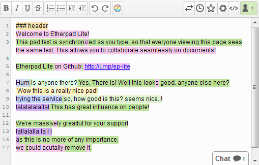
online real time collaborative text editor
a highly customizable Open Source online editor providing collaborative editing in really real-time